Overvoltage protection when interfacing an op amp to analog input

Status
Not open for further replies.
good info, as I need this as well.

regarding
R=(VAIO_MAX-VIN)/|IIC|.
what is IIC?

I was just thinking of adding a 10k resistor to the input of analog pin, as my analog source can go to 5v, but I am only interested in values up to 3.3v so I am not using resistor divider or level shifter, as that will reduce the resolution of the signal.

--
just read the data sheet, IIC is 5ma, so R should be > 280 ohms for 5v input.

--
corrected R value calculation, as VAIO_MAX is VDD+0.3 or 3.6v.
I use a lot of 3k resistor in my circuit so will try that first before using a lower value. At 3k, the current at 5v will be 467uA.
 
Last edited:
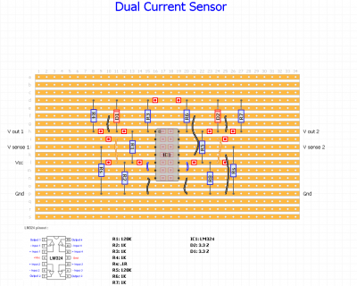
Based on all the great input I've received, here's my proposed circuit as layed out on stripboard (the red squares indicate breaks). Comments are welcome. Thanks.

Circuit.png
 
I think you are shorting the unused outputs of the opamp to GND -- don't do that. You can short the unused inputs together and to GND, but it is not necessary on analog components; usually just on CMOS logic circuits.
 
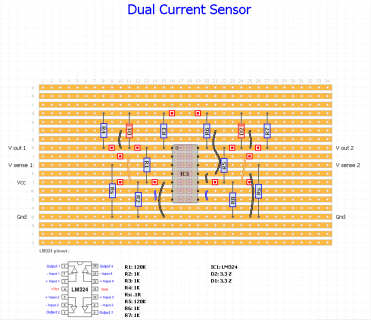
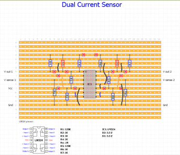
Ah, you're right and that's not what I had intended. It looks like I missed the fact that the top and bottom pinouts are mirrored across the horizontal axis. This highlights the importance of double and triple checking prior to committing to a layout! Please see the revised diagram. The intention is to tie the output to the (-) input thus creating a voltage follower. The (+) is then tied to ground. A little research on my part revealed that op amp manufacturers do indicate ways of dealing with unused inputs and a couple of sources suggested the approach I'm using here as a relatively easy way to do it. Having said that, it may not be strictly necessary though. Thx.

Circuit2.png
 

Attachments

  • Circuit2.png
    Circuit2.png
    44.8 KB · Views: 157
Thanks for the suggestion. I did initially consider the ACS712. For my application I want to measure the current draw on a small DC motor for closed loop control. The current ranges from 20ma when running with no load to 260ma fully stalled. The smallest range ACS712 I could find is 5A. Given my range, that means that I'll obtain less than 50 counts of the 1023 available for the analog input. I can't lose that much precision which is why I adopted the sense resistor/amplifier approach.
 
That'll work, but will have the same concerns about interfacing with the Teensy's 3.3 V capable inputs.
 
That might work for my application. Since I'm using the 5v tolerant GPIO pin configured as analog input on the Teensy 3.1 I don't believe the voltage level is an inherent problem, although it's unclear to me as to whether or not I still need the same protection we've been discussing for my current approach (no pun intended). Also, what I'm not sure of with this device is what resolution I can get from the 12 bit A/D converter in the 20ma to 260ma range that I'm measuring as I don't know how to calculate that from the information given.
 
Last edited:
That might work for my application. Since I'm using the 5v tolerant GPIO pin configured as analog input on the Teensy 3.1 I don't believe the voltage level is an inherent problem, although it's unclear to me as to whether or not I still need the same protection we've been discussing for my current approach (no pun intended). Also, what I'm not sure of with this device is what resolution I can get from the 12 bit A/D converter in the 20ma to 260ma range that I'm measuring as I don't know how to calculate that from the information given.

the data sheet says it provides "2.1 kVRMS Voltage Isolation" It should be well protected. 47 x gain from 5 amps you could have a max span of 106 mA if you wanted, although accuracy of that would be questionable. in the comments section of the sparkfun page there is some talk about this. hxxp://www.arunet.co.uk/tkboyd/ec/ec1SensCurr.htm
 
the data sheet says it provides "2.1 kVRMS Voltage Isolation" It should be well protected. 47 x gain from 5 amps you could have a max span of 106 mA if you wanted, although accuracy of that would be questionable. in the comments section of the sparkfun page there is some talk about this. hxxp://www.arunet.co.uk/tkboyd/ec/ec1SensCurr.htm

Thanks for the analysis. I agree it's questionable. The advantage of my current approach is that the op amp is configured for a gain of 120 from the millivolt signal across the sense resistor to the output and ranges nicely from 100mv to 3.3v. Although I haven't connected it to the Teensy yet (still waiting on my zener diodes to arrive) and written code to prove things out, if I manually brake the motor with my fingers to apply varying pressure, I witness fine grained response from my DVM when measuring the op amp output. So at least empirically, it seems to work fine.

As an aside, I've been making my own custom sense resistors by winding magnet wire around an existing resistor used only as a component base (and doubling the wire over to mitigate parasitic inductance before winding). This allows me to fine tune the sense resistor by trimming short sections of wire to get close to the exact max output voltage of 3.3v for the A/D.
 
Last edited:
Don't get carried away with accuracy. Copper wire's resistance changes by 1 % for a 3 deg. C (5 deg. F) temperature change. As the motor wears, its characteristics change; in addition (depending on what exactly you need to measure), the current will depend on supply voltage, and the temperature of the motor itself.

Motor current isn't just constant DC -- it is quite spiky; as the motor commutates (each 1/3 rotation), the current changes, and spikes could easily be 2x the DC (average) value. Thus if you scale the sense R so that a DVM (which reads average) reads 3.3 V, the Teensy will actually read lower than that (because it converts any values >= 3.3 V to 3.3 V, and therefore 'loses' that information).

Good points to make. I may be OK there because I will only reach 3.3v (or above) in the case of a full motor stall which I plan to avoid or at least keep to a minimum amount of time. So even if the voltage is reading 3.3v I can assume that the motor is stalled and cut back on the power (via PWM). If my control algorithm is any good and well tuned, then I should never (or at least rarely) reach full stall and hence never actually see the max voltage. If it helps, my application is to use the DC motor to power the take-up reel of a film scanner I'm building. I'm using a stepper with a sprocket attached to drive the film frame by frame while the take-up reel maintains tension. My goal is to run the motor continuously in a fashion so that it is able to take up slack without stalling. The goal is that the current draw measure will be sufficient for me to both control the slack and prevent the motor from being continuously overloaded. So proper slack and motor life are the two issues being addressed by this design.
 
The whole 5v interfacing issue is already resolved. The resistor divider and zener are moot and not needed.
If you are connected to an analog only pin, all you need is a 1k (>280 ohms to be exact) resistor in series to the input.
If you are connected to a digital/analog pin, then direct connection is fine.
in either case, your max value will be at 3.3v, anything above it will read as 3.3v to the ADC.

As long as 5v is not exceeded then, right?
 
As long as 5v is not exceeded then, right?

no, as long as 5ma is not exceeded.
but yes, if you are referring to digital/analog input, your'e good as long as input does not exceed 5v. otherwise, you will also need to calculate and add the series resistor.
 
Last edited:
At the start of this thread, I expressed concern over the fact that I was seeing what appeared to be temporary and intermittent spikes as high as 16v when manually stalling and un-stalling the motor. When I witnessed these "spikes", I was using a cheap (Micronta) pocket auto-ranging DVM. However, when I used two other fixed range VMs, I did not see these spikes so I'd like to believe that what I observed was an artifact of the cheap auto-ranging DVM. Still, I became concerned just in case I was wrong about that. Not knowing the magnitude of these presumed spikes, I wouldn't be able to size an appropriate resistor, hence over-voltage protection via a zener diode seemed reasonable. On further reflection, a spike that high just doesn't make sense since the op amp is being powered from a 5v supply and when saturated would only be able to output something less than that. So while there have been many great suggestions regarding over-voltage protection in this thread, I'm back to believing that no protection is necessary, I can't exceed 5v, the digital/analog input is 5v tolerant so I should be able to connect the output of the op amp directly into the analog input.

In addition, I don't believe that current is an issue as long as I stay within the 5v range. My understanding is that the input will only draw as much current as necessary based on the voltage. For reference, here's a link to that effect... (although it's for the arduino, the same should apply to Teensy)

http://forum.arduino.cc/index.php?topic=51967.msg370556#msg370556
 
Now that I have connected the circuit to the Teensy, I though I'd post a followup.

I ended up placing a 4.7k resistor on the op amp output to the analog input (A9 programmable input). I decided that the zener would be overkill so I did not use it. Also the output of the op amp at saturation is slightly less than 3.3v so I don't believe there's any danger of over driving the input.

One thing that I did observe is that when watching the count on the serial monitor, I see quite a bit of variation. For example, when the motor runs with no load, the count jumps around by as much as 100 counts. Since it's a 3.3v range with 10 bit resolution (1023) that's approx 3mv per count. So that equates to as much as 10% variation (300mv) during steady state operation. I tried some software averaging of the signal, and that helps a significantly - even to the point where it's workable for my application, but I'm still concerned/surprised/bothered by the variation.

I tried feeding a fixed 3.3v signal (using the zener to produce that directly from the regulated 5v supply), and I still see some variation. I see the count vary from 968-1023 (a difference of 55 or 5%). In all cases, I'm using an external 5v supply.

I'm puzzled by this variation. Is this amount of jitter expected, or am I missing something fundamental? Any thoughts?
 
Last edited:
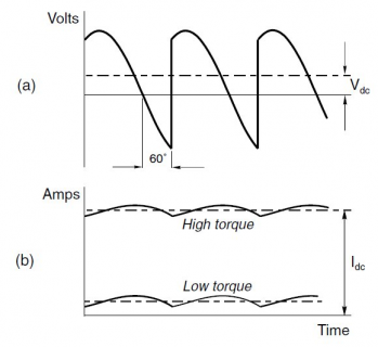
That's not surprising -- here's a picture of (idealized) motor current for a simple brushed DC motor. In reality there are larger spikes as it commutates.
motor.png

In addition, as the motor wears (and the brushes 'settle in', you'll get different results; you'll also get different results from running forward and reverse.
 
Thanks for the graphic. Yes, now that you mention it, it makes sense that the continuous switching that's going on due to commutation creates lots of noise. Recall that I added a 4.7k resistor as a safety measure on the op amp output. I tried adding a .1uf capacitor thus turning it into an RC filter and that made a huge difference. I'm seeing far less variation now. I prefer the hardware filtering approach over the software approach since the former should introduce far less delay.

I haven't yet added PWM control of the motor. I am a little concerned that that will add more noise, but hopefully my output filter will be sufficient to deal with that as well.
 
FWIW, I am using ACS712 and connected the output directly to teensy 3.1 analog input pin and not getting correct reading. I use the 5amp module and since I am measuring DC current, simply connected the line in reverse polarity so the max reading is 2.5v and voltage goes down as current flows. My test circuit correctly makes ACS712 generate voltage from 2.5 down to 2.0, but the teensy analogRead always reports 2.5v, until the actual volt is around 2.2-2.3, then the analogRead will suddenly jump down to that reading, and they hovers around that reading before jumping straight down to 2.0-2.1 reading. The teensy does not do anything other than print analogRead every second. And I tested connecting the analog input to 3.3v and gnd and get the correct value. Not sure why I'm not getting correct reading.
 
For the same amount of filtering, both the hardware and software approach will have the same delay.

PWM will introduce more ripple -- but you should PWM at frequencies higher than the response time of the motor (that's hard to define). PWM behaviour is not trivial for a DC motor -- a (large) capacitor across will defeat the PWM. Best is a switch (FET) that PWMs. You may need a zener (protection) across the FET; depends on the motor.
 
jp3141 - Yes, I believe there's no free lunch, so either approach of filtering (software vs. hardware) will introduce latency. Maybe I'm thinking that as a matter of practically, the time constant on the RC filter is such that the latency will be less than multiple averaged samples read by the software at 1ms intervals. I'll look into how to vary the PWM frequency on the Teensy 3.1 and experiment with that if I run into problems. I need to try some experiments. I plan on using a PID algorithm to maintain constant current draw from the motor (current reading=measured variable, PWM to motor=control variable). Again, all I'm trying to do is to use the motors to take up slack and maintain proper tension on a take-up real. Also, the goal is to not burn them up. Thanks again for all the suggestions.

doughboy - Even though the values are jumpy, do the count values makes sense with respect to their calculated values? With a 3.3v Vcc, I believe the 0 current reading corresponds to a count of 512 and Vcc/2 = 1.65v. Are you using an external 5v supply? If so, are the grounds tied together? Here's a link I found which indicates that a load should be placed on the output rather than directly connecting to the analog input. They suggest using a voltage divider to provide a 4.7k load and to scale the reading to 3.3v.
http://electronics.stackexchange.com/questions/126805/acs712-to-arduino-due-adc-input
 
Last edited:
Status
Not open for further replies.
Back
Top