Teensy power consumption and PWM resolution at high frequencies.

Status
Not open for further replies.

taz-nz

New member
Hi,

I'm throwing myself in the deep end when it comes to microcontrollers & electronics. :p

There are a couple of details I need to confirm before I start making purchases.

1) Will the Teensy 3.2 run off the 5V(+/-5%) 0.3A standby power supply on a Mean Well HRPG-450-15 ?

2) What PWM resolution can I get when, producing a 250Khz PWM signal ? 8bit-10bit (256-1024 steps)?
I need at least 8bit, but 10bit would be great, because in my application I only expect to use for 33-100% duty cycle, so effectively only 2/3 of steps are useable for me.


The project is to control my water cooling setup in my pc. I'm going to take it in these steps.

1) Get Teensy 3.2 running off 5V 3A standby rail on PC power supply.

2) Link PC power button to Teensy, and link Teensy to motherboard power switch headers and have teensy turn PC on when PC power button pressed.

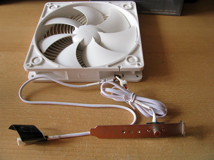
3) Get Teensy to control fan speed of three Silverstone AP182 fans, by replacing stock manual 10K pots with Analogue Devices AD8403AN10 digital Potentiometer, Fan speed will be adjusted based on water temperature from Phobya G1/4 Temperature Sensor (thermistor) connected to Teensy.
(Fans have built in IC controller that can't be feed PWM DC, so this is the only practical way to control them.)

4) Get Teensy running from Meanwell HRPG-450-15 power supply Aux power connection.

5) Get Teensy to turn on both PC and Mean Well power supply (via remote power switch pins) when PC power button is pushed, and turn off Mean Well Power supply when PC shuts down.

6) Get Teensy to Control DC Step Mode Power Supply with PWM signal, adjusting duty cycle based on temperature signal from Analogue Technologies ATH10K1R25
thermistor.
(PWM signal will control custom SMPS, which will power Thermoelectric TEC1-19940 Peltier, that will be cooling CPU.
 
The bus clock which is responsible for the PWM frequency and resolution is derived from the CPU clock by integer division to remain below the limit of 60MHz. Thus, clocking the T 3.2 at 96MHz will give a bus clock of 48MHz, and 36MHz at F_CPU=72MHz.
A PWM frequency of 250kHz will then have 192 ticks @ F_BUS=48MHz and 144 ticks at 36MHz - both below the desired 8bit resolution.
It is possible to overclock the bus, though, without modifying the CPU clock to run with a divider=1. In that case, you’ll get 384 or 288 ticks which is higher than the 256 ticks from 8bit.
Overclocking the CPU at 120MHz (or using a T 3.5 or 3.6) will allow you a „legal“ bus clock of 60MHz with 240 ticks, or overclocking at 120MHz with 480ticks, the latter coming close to 9 bits.

Edit: I see only now that it‘s about controlling fans, IMHO 6 bit (64 steps) should be largely sufficient for a decent speed control.
 
1) Will the Teensy 3.2 run off the 5V(+/-5%) 0.3A standby power supply on a Mean Well HRPG-450-15 ?

Yes. The power consumption is about 45 mA, well below its 300 mA capacity.

You can also underclock Teensy and/or use Duff's Snooze library if you want to reduce its power consumption.


2) What PWM resolution can I get when, producing a 250Khz PWM signal ? 8bit-10bit (256-1024 steps)?

At 250 kHz you'll get 192 steps, if running at the default 96 MHz, or at 48 MHz (which should be plenty for this sort of project).

However, if you're PWM controlling fans made for a PC, almost all of them are designed for 25 kHz PWM, not 250 kHz.

www.formfactors.org/developer/specs/4_wire_pwm_spec.pdf

Look at the spec on page 9 in section 2.1.4, which says 28 kHz is the maximum acceptable PWM frequency.

You should also be aware the Teensy pins should only be used directly with 4 wire fans. If using a 3 wire fan, you'll need to use a transistor circuit for the PWM signal to switch the fan's power. Only the 4 wire types take regular power and a control signal, with the switching built inside the fan.

You might also wish to use the FreqMeasure or FreqMeasureMulti library to read the fan's tachometer output. When estimating frequency, don't forget to divide RPM by 60, and multiply by 2 (since almost all PC fans give 2 pulses per rev).

To detect a stalled fan, you'll also need to use something like elapsedMillis to implement a timeout, where FreqMeasure doesn't give you any more pulse timing info for too long. Fairly easy to do, but important to realize it's needed and to make sure you test your code by actually stalling a fan.
 
Last edited:
The bus clock which is responsible for the PWM frequency and resolution is derived from the CPU clock by integer division to remain below the limit of 60MHz. Thus, clocking the T 3.2 at 96MHz will give a bus clock of 48MHz, and 36MHz at F_CPU=72MHz.
A PWM frequency of 250kHz will then have 192 ticks @ F_BUS=48MHz and 144 ticks at 36MHz - both below the desired 8bit resolution.
It is possible to overclock the bus, though, without modifying the CPU clock to run with a divider=1. In that case, you’ll get 384 or 288 ticks which is higher than the 256 ticks from 8bit.

Thanks, that's just the information I needed, I knew there as a relation to the CPU Clock, but wasn't sure if it was based on CPU clock or a base clock, and wasn't sure what the base clock was. I abandoned the idea of using a Arduino Pro Mini when I realise I'd only have crazy low resolution at 250Khz.

I'll stick with the Teensy 3.2 because of size, but if I overclock it to 96mhz, like you say I'll get 192 steps at 250Khz, and I'm using only 2/3 duty cycle range that give me about 127 steps which is 7bit, which I can live with, I might look into bus overclock too because that will effective double my resolution as you say and give me near 256 steps of usable control range.

I need the high PWM frequency to drive a DC controller for a peltier efficiently, and a good number of duty cycle steps to have fine control.

Yes. The power consumption is about 45 mA, well below its 300 mA capacity.

You can also underclock Teensy and/or use Duff's Snooze library if you want to reduce its power consumption.

Thanks for the info, looks like I've got lots of head room, but seems I'll need it because I'll be running CPU overclocked and possibly the bus too.

At 250 kHz you'll get 192 steps, if running at the default 96 MHz, or at 48 MHz (which should be plenty for this sort of project).

However, if you're PWM controlling fans made for a PC, almost all of them are designed for 25 kHz PWM, not 250 kHz.

www.formfactors.org/developer/specs/4_wire_pwm_spec.pdf

Look at the spec on page 9 in section 2.1.4, which says 28 kHz is the maximum acceptable PWM frequency.

You should also be aware the Teensy pins should only be used directly with 4 wire fans. If using a 3 wire fan, you'll need to use a transistor circuit for the PWM signal to switch the fan's power. Only the 4 wire types take regular power and a control signal, with the switching built inside the fan.

You might also wish to use the FreqMeasure or FreqMeasureMulti library to read the fan's tachometer output. When estimating frequency, don't forget to divide RPM by 60, and multiply by 2 (since almost all PC fans give 2 pulses per rev).

To detect a stalled fan, you'll also need to use something like elapsedMillis to implement a timeout, where FreqMeasure doesn't give you any more pulse timing info for too long. Fairly easy to do, but important to realize it's needed and to make sure you test your code by actually stalling a fan.

Thanks for the info about fan control, I might end up using the tachometer feature as part of my fan control setup.

I wish I could just use PWM to control the fans I'm using, but they basically have a PWM controller build in that freaks out when you try to feed them with PWM, they make a horrible noise and the tachometer output fails. The PWM question was for peltier control, a separate issue.

t0byrYd.png


The fans are 180mm and very high airflow and have very good static pressure, and they come with the option to control them with a remote 10K pot, so since I can't control them with traditional PWM, I decided I'd control them by automating the Pots instead, that's where the Analogue Devices AD8403AN10 digital Potentiometer comes in, I can control it via SPI connection to the Teensy 3.2 and it will in turn control the three fans.

I found this helpful guide to running the AD8403 for the Arduino, http://matthewcmcmillan.blogspot.co.nz/2013/10/arduino-using-digital-potentiometers.html and I'm guessing it will not take a lot of work to get the same setup running on the Teensy.
 
That AD8403 code looks like it ought to work, though it never actually configures the SPI speed and other settings. I'd recommend adding SPI.beginTransaction and SPI.endTransaction in its digitalPotWrite() function, so you know for sure the SPI is properly configured.
 
for the teensy on pc setup if you get a small 20-pin or 24-bit extend cable, you can get the GREEN wire which turns the pc on and the 3.3v power lines tapping into those lines, without touching the mainboard or psu wiring.. then you just plug the cable between the psu and mainboard
 
Status
Not open for further replies.
Back
Top