Audio Library

Status
Not open for further replies.
Well, it seems like it was a memory leak caused by opening all those files and then never closing them again. I blame the confusing way C frees memory... or doesn't.

As you can see here they never free the entry object:
http://arduino.cc/en/Reference/FileRewindDirectory

But I think what's happening is the compiler frees the object when it goes out of scope, but not when you overwrite it (I've gotten too used to languages that have full garbage collection) and they wrote the example using recursion which just happens to make it so each entry object is automatically deleted as it's used. In my case, I was looping inside a function, and never closed the files, so only the last file would ever go out of scope... and even that depended on where I allocated it.
 
I asked about this a long time ago, but I noticed the volume control doesn't work for the line-out. There was talk about implementing it for that. Did that ever get done? Or is there a way to adjust the volume by adding a mixer or something?
 
You know this library was confusing as hell to me when I first started using it, but I think I understand now how the whole chaining objects together thing works now. I like it, makes a lot of sense. And I was able to add that volume control I wanted, because it turns out the mixer object has a gain setting for each channel. I set it up like so:

Code:
AudioPlaySdWav     wav;
AudioPeak          peak_L;  // The reason we have two seperate peak objects is because the peak object doesn't know which channel it is attached to and maintains an internal state of min and max sample since the last query.
AudioPeak          peak_R;
AudioMixer4        mix_L; // Used for volume adjustment.
AudioMixer4        mix_R;
AudioOutputI2S     i2s;

AudioConnection c1(wav, 0, peak_L, 0); 
AudioConnection c2(wav, 1, peak_R, 0); // Only need the left one since our audio is mono.

//AudioConnection c3(wav, 0, i2s, 0);
//AudioConnection c4(wav, 1, i2s, 1);

AudioConnection c3(wav, 0, mix_L, 0);
AudioConnection c4(wav, 1, mix_R, 0);
AudioConnection c5(mix_L, 0, i2s, 0);
AudioConnection c6(mix_R, 0, i2s, 1);

  audioShield.enable();
  audioShield.volume(1.0); // Only controls I2S volume.
  audioShield.unmuteLineout(); // By default the audio shield mutes the line out pins.
  
  mix_L.gain(0, 0.1); 
  mix_R.gain(0, 0.1);
 
There is one issue I'm still having. I'm not sure if it's the cheap 3W amplifier I'm using which is at fault or the audio module itself, but when I have no audio playing and I read the filenames from the directory, I can hear the data transfer going on. It's not particularly quiet. I'd say 5% of full volume. I can also hear quiet pops on my speaker from the sonar module I'm using.

I've tried powering the board both from a 1.5-2A 5V wall adapter, and from the USB. Sounds exactly the same. There is a spot on my amplifier module for another capacitor, bit I kind of doubt that's where the issue is. I have an adafruit LED module attached as well, and I don't seem to get any noise from that.
 
Hm, I just tried connecting headphones and I don't get any of the SD card noise. I suppose it's time to try adding that capacitor to the amplifier module.
 
There is one issue I'm still having. I'm not sure if it's the cheap 3W amplifier I'm using which is at fault or the audio module itself, but when I have no audio playing and I read the filenames from the directory, I can hear the data transfer going on. It's not particularly quiet. I'd say 5% of full volume. I can also hear quiet pops on my speaker from the sonar module I'm using.

I've tried powering the board both from a 1.5-2A 5V wall adapter, and from the USB. Sounds exactly the same. There is a spot on my amplifier module for another capacitor, bit I kind of doubt that's where the issue is. I have an adafruit LED module attached as well, and I don't seem to get any noise from that.

An unfortunate thing about audio signals near digital signalling is that the rapid transitions between low and high states on the digital pins near audio signal lines often make an impression on the audio signal which is all too easily amplified. EDIT: Also, the 'hit' on the supply by both rising and falling transitions on digital circuitry is bigger relevance than proximity of signal traces.

Suggestions:

(1) Route all digital signals as far as physically possible from audio signals in your design.
(2) Do a little reading on ground loops and try to identify if your design could be suffering from anything related.
(3) Read some of the things returned for Google search: https://www.google.com.au/search?q=reduce+noise+from+digital+circuitry+near+audio+signal+circuit
 
All I have is the teensy mounted on the audio module, an ultrasonic distance sensor connected to a couple pins, a TLC59711 led module connected to a couple pins, and the amplifier connected to the line out. The power connections for all four devices, both ground and 5V, are connected at the same point - the end of the cable on the power adapter. Moving the cables around and spreading the modules apart does not change the noise level.

If I have a ground loop, it would be due to the amplifier being grounded on the line out. I've tried disconnecting the ground to the line out but that only makes the problem worse.

I have done loads of reading up on ground loops because I designed my own audio board a while back and I had serious noise issues when the amplifier was powered by the same battery, but that noise was so loud you couldn't hear the audio at all. This is like there's noise on the 5V rail from the SD card access. I suspect the Teensy and/or the amplifier lack sufficient decoupling caps on the power input. Not that I'd expect the Teensy to have big caps on the input. Hopefully adding a capacitor to the amplifier will do the trick.
 
If capacitor on the amp module doesn't make great enough effect you can consider putting a largish cap (=>100uF) on the 3.3V pin as close to Teensy+Audio Adapter as possible - possibly more/better effect on the 3.3V output of the built in LDO regulator but it may be relevant to give the 5V 'VIN' pin a similar ballast.
 
I put a 47uF capacitor on the amp. I'm not sure if it helped. It may have reduced the noise by half. Hard to tell.

Adding a second to it definitely didn't help. Adding a 47uF to the 3.3V power rail on the Teensy via the pins for the volume pot also didn't help. I have yet to try one across the Vin power input.

I then decided to try a Pi filter like this:
http://www.maximintegrated.com/en/app-notes/index.mvp/id/4713

But I only had a 180mH and 47uF caps to work with. Still, it seemed to help noticeably when placed on the amp's power supply lines. I'm sure the correct values would be more effective.

I guess I'll try using the same inductor and caps (1mH and 25uF) as in that schematic in my final circuit.

/edit

Oh, and disconnecting the ground from the line out just makes the noise come back in full force.
 
Last edited:
.... Adding a 47uF to the 3.3V power rail on the Teensy via the pins for the volume pot also didn't help. I have yet to try one across the Vin power input. ...

/edit

Oh, and disconnecting the ground from the line out just makes the noise come back in full force.

You can't disconnect that ground between line out and amp.

I didn't mention your volume pot, just try a biggish polarised electrolytic capacitor with positive connected to 3.3V pin on Teensy 3.x and negative connected to GND pin on Teensy 3.x - one per 3.3V pin on the Teensy can't hurt a thing (at least if connected properly) and can have a huge influence in terms of reducing noise.

Edit: To have best effect the caps need to be as close as possible (in reference to track length) to the 3.3V pins on the Teensy as possible.


The smaller ( the values of) your pull-up (or pull-down) resistors on any digital line the bigger the 'thump' on the power rail in use the more (and more) you need extra ballast on that power rail to cope with the 'thumping' that switching IO puts on it.


One of our main bread winners at my work is preamps for acoustic guitars. One of our more recent models includes a guitar tuner implementing an AtTiny84. I slowed the IO with significant thump (driving a seven seg display and 3 more LEDs around it) down a lot and the chief electronics engineer still ended up putting 220uF capacitance across the 9V battery and across the output from the LDO 5V regulator driving the AtTiny in his efforts to reduce the noise from just switching individual LEDs (inclusive elements in seven seg) when the tuner was running, This treatment also reduced the hiss type noise just having the AtTiny running so close to audio signal circuitry introduced.


In case you don't know; caps calculate exactly opposite to resistors where putting them in parallel adds their capacitance together and putting them in series has the effect on capacitance which putting resistors in parallel has on resistance; this to say that two 47uF caps in parallel is a lot closer to 100uF than if in series or something like that.
 
Last edited:
I used the volume pot connection for the capacitor because it was just a convenient place to access the 3.3v and GND rails that seemed close enough to the pins to get the job done.

And yes, I'm aware how wiring caps in series vs parallel works. The extra 47uF cap I stuck on the amp which did nothing to improve things was in parallel.

I think the Pi filter will do the job. I didn't even use the right components for it and I got a major reduction in noise.
 
In [https://github.com/PaulStoffregen/Audio/blob/master/synth_waveform.cpp#L93]synth_waveform.cpp[/ul], output is hardcoded to the left channel only.
Code:
  //          L E F T  C H A N N E L  O N L Y
Is this just a temporary restriction? If so, what is the best way to relax this to allow output to right channel as well:
- pass a L/R channel identifier
Code:
void AudioSynthWaveform::update(short channel)
- duplicate the code to synth_waveform_R.cpp (seems ugly)

The idea is to send different waveforms to L and R channels, so they would need separate variables for their internal state.
 
If this object is like all the others, then I think that comment is misleading.

As I understand it, there is no left or right channel in the audio library. There are objects, and each object can have multiple inputs and multiple outputs, called channels. Each input or output from an object can only be connected to one other object, hence the mixer object to mix multiple channels.

The first object in your chain is typically something like a WAV object or line-in which outputs two channels: 0 and 1 ... left, and right. As far as all the other objects are concerned though these could be anything, and ultimately the left input could be routed to the input for the right channel on the last object in your chain.

Also, each object is an object, so when you create it, it gets its own set of internal state variables.

I haven't looked at the synth object, but I would assume that it has a single output channel - channel 0, and whoever wrote that function assumed channel 0 is always the left channel, but that is incorrect. It is just channel 0 and you can feed channel 0 into any input channel on any other object you create.

So... if you want to sythesize both a left and a right channel of audio, then you would create two synth objects, and one output object (which will have two inputs) and then route channel 0 from each of the synth objects into channel 0 and 1 of your output object.
 
For those who want to play with wavetable synthesis or use custom waveforms, I have now made a "Wave Tool",
which includes 4000+ Waveforms incl. C-Headers. Use the slider to select waveform, copy code, use it.

http://tech.datanoise.net/wavetool/

These are single-shot waveforms from the AKWF Free Single Shot Sample collection.
All samples are resampled to 1024+1 samples to be used in Roel's version, which uses 1024+1 instead of
256+1 samples (see page 26/27).
 
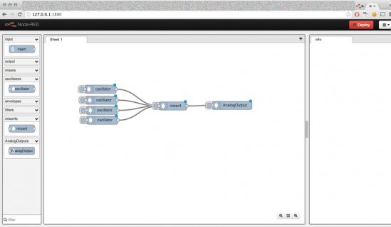
I am also thinking about a "visual-programming" interface for building projects using the teensy libraries (for me it would be more
audio library oriented).
screen.jpg

here is a draft.
 
Code:
  //          L E F T  C H A N N E L  O N L Y

That was me. Originally, that library handled both channels, as did a couple of others that I wrote, until it was pointed out to me that it isn't necessary in those cases. The two channels can be handled independently and, as it turns out, it is more efficient to do so.

Pete
 
Paul,

Puredata (http://puredata.info/) can do a lot. in fact, the beat detector I am working on, was already build in PD. If there is a possibility to convert from PD to a Teensy(arduino ) compatible file(library) I would be very happy..

regards
rob


This looks really awesome!


I've dreamed of doing this, but always considered it far beyond my limited time and GUI programming effort.

Is this available on github or a web page somewhere? I'd love to give it a try.
 
Puredata was initially much of my inspiration for the connection-oriented design of this library.

In the very early days, pretty much the May to December 2013, I struggled with how to structure this library to make best use of the Cortex-M4 hardware efficiently, yet provide a highly flexible model like Pd.

Puredata has 2 types of connections, represented with thin and thick lines. The audio library connections only correspond to the thick lines, which transport actual audio data. The thin lines in Pd, for events and numerical values (usually associated with configuring something) are done by the Arduino sketch calling functions from each object.

The other key difference is data types. Like Pd, the audio library tries to use floating point for parameters you change with the functions. But the audio data is 16 bit integers, because the Cortex-M4 has special DSP instructions for 16 bit ints. Unfortunately, this means the audio library will never be able to very fluidly mix control data and audio data like Pd can. It also means the object tend to have only higher level functionality, whereas Puredata lets you mix high level objects with very low level mathematical operators and other stuff. I recently added queue objects to get at the raw data from Arduino sketches, but they're a far cry from the amazing ways you can mix real time signals and math operators in Pd.

Eventually, when I get more time to really work on the Audio library, I'm going to add more objects that take a control stream as input. We already have a FM sine wave. A signal controlled filter and other stuff, and more synth objects to create ramps and other useful control signals, will be on my todo list. A Cortex-M4 isn't ever going to give you all the awesome flexibility Pd can running on a multi-GHz PC, but hopefully a set of objects with control signal inputs can provide a pretty useful subset.

I'm really interested to try Syso2342's GUI program. Long-term, I think it could really help people to understand and more easily build the object instances to copy into their Arduino sketches. I'd also like to use screenshots of the objects in the library documentation. It's really a piece of this system I never imagined I'd be able to create, so just seeing that screenshot has me really excited.
 
Status
Not open for further replies.
Back
Top