Audio For Teensy3 - What Features Would You Want?

Status
Not open for further replies.
Just a quick update, in case anyone's wondering what's up with the audio board.

We've been testing and packaging them today. There was a minor setback where 3 of the pads (for the optional volume/parameter pot) didn't line up well with the bed-of-nails test fixture. I ended up removing those nails and Erin is manually checking those 3 pins on every board with a multimeter.

My hope is to get the board buy-able on the website sometime tomorrow or Saturday. We'll start actually shipping boards on Monday. The first beta software release will be on Monday.
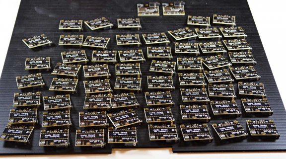
audio_1st_batch.jpg
(click for large image)
 
Ok, here's the link to order an audio adaptor board.

http://www.pjrc.com/store/teensy3_audio.html

Odds are good we might start shipping them today, but if not, they'll certainly ship on Monday.

As you can see, I still have a lot of work to on documentation, and an initial release of the library. That will be coming this weekend. The library will be "beta" for some time, partly because many planned objects and examples are still missing, but also because the APIs might incompatibly change.

I'll post an announcement next week, once the software and documentation are online. But for anyone who's been following this thread, you can get a board early if you want. ;)
 
Awesome. Shame I'm in the UK, will try and get cool-components to get some in and save me the shipping!

Also Paul, can you give any guidelines on how to help contribute to the audio library once it's up?

Thanks.
 
I really can't wait to test the Audio library and to adapt my USB Audio library to integrate with it :)
 
I decided to reply to the other thread here since it was off topic there:

Feedback from several people indicated line in/out would usually involve soldering wires to a front panel or some other board. I really did consider adding more jacks, RCA or headphones, but ultimately small size and lower cost won over convenient jacks.

Small size is important to me. Even more so than lower cost. But for my purposes I intend to install these in both large and small enclosures along with an amplifier module of suitable size. For the small enclosures, a little 3W amplifier module will do, and as those don't have jacks on them anyway, solder pads are fine. But for larger projects, a 10W or greater amplifier is needed, and those almost always have a 3.5mm jack for input. And the convenience of just purchasing an audio cable and plugging it in cannot be understated. For one-off projects, sure, it's easy enough. But if you start selling in some volume, there's no joy in spending hours crimping hundreds of connectors.

What would be really sweet would be if there were a way to select what pins the 3.5mm jack is connected to. If you added some solder jumpers to the bottom of the board it wouldn't cost anything or increase the size of the board and you could have one pair select between gnd or vgnd, and several more would allow you to select what the tip and ring are connected to. This setup would even allow for weird outside cases like headsets which have a mic and an earpiece on a single jack.
 
Last edited:
Heh, I also emailed Pieter. He expects to receive them in the coming week :)

Regarding the board: I'm very happy with it having a 3.5mm jack, a small headphone amplifier and a SD-slot. Why? It makes prototyping just so much smoother. If you want to mass produce (100+) anything and there are bits you don't need, then you're gonna make a new PCB anyway.
 
Probably going to order this board, but some question

What is the technical name of that header? (trying to find it otherplaces, they looks nice for some other projects I have)
The flash-chip, are you going to sell that?, I'm not very keen on going to mouser for an order, which will give me $30 in shipping.

Is there any plans for adding midi input?, or are there enough io left to make some adapter?
 
What is the technical name of that header? (trying to find it otherplaces, they looks nice for some other projects I have)

They're sometimes called "spacer" headers.

The flash-chip, are you going to sell that?, I'm not very keen on going to mouser for an order, which will give me $30 in shipping.

There is currently no software support for the 8 pin SPI flash chip. Don't waste $30 in shipping for it, since you won't be able to use it. Well, not unless you write all the code, of course!

Is there any plans for adding midi input?, or are there enough io left to make some adapter?

A big 5 pin DIN connector would probably increase the PCB size by 50%. It seems unlikely it will be added.

But there are plenty of pins unused by the audio board, including pin 0 to receive 31250 baud serial. You could probably wire up a 5 pin DIN and PC900 optocoupler and run the signal to pin 0, using the MINI 3.2 library.

At the end of the audio adaptor page is a diagram which shows the pins used by the audio and SD card.

http://www.pjrc.com/store/teensy3_audio.html

11 I/O pins are unused by the adaptor, plus the CS pin for the SPI flash, which isn't connected unless you solder a flash chip. But there's not much point to adding that chip yet, because there's no software support at this time.

The software does support playing WAV files from the SD card, and short clips from the internal flash of the MK20 chip on Teensy 3.1.
 
Probably going to order this board, but some question

What is the technical name of that header? (trying to find it otherplaces, they looks nice for some other projects I have)


You can get them here:
http://www.digikey.com/product-sear...ee=0&rohs=0&quantity=&ptm=0&fid=0&pageSize=25

The stack height parameter tells you the distance between the two boards you're mating. So a .200" stack height is a header with two of the black plastic spacers butt up against one another, while a .300" will have an empty space the thickness of one of those spacers between, like the one in the PJRC store. The $20 one there has the long pins on one side like PJRC, suitable for breadboards, while the $11 one has short pins on both sides.
 
11 I/O pins are unused by the adaptor, plus the CS pin for the SPI flash, which isn't connected unless you solder a flash chip. But there's not much point to adding that chip yet, because there's no software support at this time.

The MCLK pin can be used as well if you don't have the flash chip in place, I assume.
 
Is there any plans for adding midi input?, or are there enough io left to make some adapter?

There is already a USB connector, and a very capable USB MIDI implementation - just select it from the menu. (this does require a USB host, such as a computer, unlike the point-to-point DIN MIDI. On the other hand, throughput is much higher so you don't get congestion botlenecks).
 
They're sometimes called "spacer" headers.

Great, will try to look for that.

There is currently no software support for the 8 pin SPI flash chip. Don't waste $30 in shipping for it, since you won't be able to use it. Well, not unless you write all the code, of course!

If it was sold in the same manner as you sell the headers and the thumbweel resistor, I would'nt waste shipping :), but if there is support or not, with time, someone would do it, I would definately try to do something when I get up to speed on this, but wanted to check before buying the audioadapter.

A big 5 pin DIN connector would probably increase the PCB size by 50%. It seems unlikely it will be added.

But there are plenty of pins unused by the audio board, including pin 0 to receive 31250 baud serial. You could probably wire up a 5 pin DIN and PC900 optocoupler and run the signal to pin 0, using the MINI 3.2 library.

At the end of the audio adaptor page is a diagram which shows the pins used by the audio and SD card.

An pinout would also be ok.
The picture is fine, if it was overlayed with the teensy layout :) (I really dig the card that comes with teensy 3.0 and 3.1, everyone should make something like that)
Hm, of course, there is an sd-card, that might reduce the need for the flash somewhat, how is the speed of reading from the sdcard comparing to the flash? (idea for the flash was to upload samples..)

http://www.pjrc.com/store/teensy3_audio.html

11 I/O pins are unused by the adaptor, plus the CS pin for the SPI flash, which isn't connected unless you solder a flash chip. But there's not much point to adding that chip yet, because there's no software support at this time.

The software does support playing WAV files from the SD card, and short clips from the internal flash of the MK20 chip on Teensy 3.1.

btw, I didn't get email to tell that someone answered this post, I had to go looking for it, even if I turned it on, is it turned of serverside?
 
Status
Not open for further replies.
Back
Top