Series resistor, HCT245, Adafruit

Status
Not open for further replies.

RichardFerraro

Well-known member
RECOMMENTATIONS:

I see that you are now recommending 5v thereby requiring the HCT245.

I note that Adafruit is warning that a 300 ohm resister should be used before the first led.

I also note that careful layout and power application is essential.

MY SYSTEM:

I am using sticks from Arduino mega with strips from Adafruit and two 144 led/meter strips for ledLightingHut.com.
(On arrival one worked and one did not.) These include a 300 ohm series resister at the input pad to the strip.

MY PORT:
I will be using the Teensy 3.1 when the HCT245's arrive.

QUESTION:
Do you recommend
a) reducing the value from 300 ohm to tune for best signal characteristics?
b) moving the resister to the output of the HCT245's?

thank you,

Richard
 
RECOMMENTATIONS:
I see that you are now recommending 5v thereby requiring the HCT245.
Richard
5V for what ?

I note that Adafruit is warning that a 300 ohm resister should be used before the first led.
Richard
What Led ?
I am using sticks from Arduino mega
Richard
What Sticks ?
with strips from Adafruit
Richard
What strips ?
and two 144 led/meter strips for ledLightingHut.com.
Richard
Again, what LEDs ?

:)
 
Most importantly, 144 LED/m NeoPixel WS2812B Digital Intelligent RGB LED Strip Light. Adafruit.com
Also sticks are from Adafruit: NeoPixel Stick - 8 x WS2812 5050 RGB LED with Integrated Drivers LedLightingHut.com
Waiting delivery on: 24x30 NeoPixel WS2812B Digital Adreesable Flexible LED Dispaly Screen Panel (Matrix), 25x50CM, DC5V Input LedLightingHut.com

By 5 volt I meant not driving the WS2812B directly from the 3.3v Teensy outputs; rather, going through the HCT245 driver chip.
 
Until recently, every WS2811 and WS2812 I personally tested, and many I've seen (in person) other people use, the ones people reported using on the internet all worked with 3.3V signal input.

But some of the newest ones are confirmed to NOT work with 3.3V signals. I have one of those strips on my desk right now. It simply ignores the 3.3V signal. You must use a 74HCT245 or similar chip to increase the signal from 3.3 to 5V.

Normally the resistor would go between the output pin of that chip and the wire going to the LEDs. The specific resistor to use can vary, depending on the type of wire. Values can range from 50 to 330 ohms. Often no resistor works, especially if your wires are short. The optimal resistor depends on the type of wire you use. I'd recommend trying 100 ohm first.
 
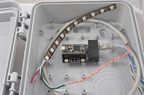
PJRC is making an interface board for OctoWS2811. It should be available sometime in March. Here's a photo of the prototype.

octo28_proto.jpg
(click for full size)

Under the Teensy (not visible in this photo) are the 74HCT245 and 100 ohm resistors. The 8 signals are delivered to a pair of RJ45 connectors meant for CAT5 or CAT6 ethernet cable. Ethernet cable is excellent for these signals, with plenty of bandwidth and it's precisely matched to the 100 ohm resistors, so you get the best possible signal delivery. Just take any ethernet cable, cut in half, strip away the jacket and use the pairs to feed each LED strip.

Ideally, you should wire large LED projects with the power supplies directly feeding the LEDs and the data+ground from Teensy meeting the power's ground at or near the LEDs. This approach with ethernet cables naturally encourages that wiring style. It also makes swapping out the electronics or disconnecting the display easy, since the cables just unplug.

This new board has mounting holes for a CableGard CG500 enclosure. Often they're called a "Coax Demarcation Enclosure", since they're sold for cable companies to install signal splitters on the sides of buildings. There enclosures are weather resistant and very strong, and available cheaply from several places.
 
Status
Not open for further replies.
Back
Top