Teensy 3 SPI Basic Clock Questions

Status
Not open for further replies.
Yes, but it's not just length - it's a combination of data rate and length. The slower the data rate, the longer runs that I can get. I don't have an oscilliscope, unfortunately - just a seale logic analyzier. To be fair, a 10Mbps data rate is fantastic, but I'd love to be able to pull everything out of here that I can, if possible.

This is an area of electronics where my "off the top of my head" knowledge falls pretty short - what kinds of things would you suggest for enhancing the signal in the line? (How much of this is related to the teensy 3's data pins being 3.3v instead of 5v?)
 
Last edited:
what kinds of things would you suggest for enhancing the signal in the line?

I'd try CAT6 cable, with the clock and data on 2 of the colored wires, and all 6 other wires (or at least all 4 white wires) connected to ground. The ground wires must connect to Teensy 3.0 and also to the LPD8806. I'd use 100 ohm resistors between the Teensy 3.0 pins and the colored wires.

This is called source termination. There are better ways (used by USB, Ethernet, even DDR2 memory), but they usually result in lowering the signal voltage, so they don't tend to work with ordinary chips unless you build a very special driver circuit.

(How much of this is related to the teensy 3's data pins being 3.3v instead of 5v?)

On the OctoWS2811 page there's a section called "Signal Quality" that talks about these problems. The issue is basically the same, except the 3.3 volt level is closer to the threshold that a LPD8806 recognizes high to low, so any ringing or cross-coupling of signals from the other wires has less voltage margin than if the signal had been 5 volts.
 
I'm seeing this glitching with a fairly short run of wires (like ~3 inches) from the teensy directly to the lpd8806's - I've got the data, clock, and ground lines from the far end of the strip grounding to the teensy's ground at the moment as well.

From experimenting, it looks like I can push up to 150 leds at 20Mbps before I start to see glitches towards the end of the line with the above setup. (Of course, combine that with a multiplexer and I can have N-150 led strips that I can push, in aggregate, at 20Mbps - the library allows you to define an arbitrary object as a "selector" for a line - so while right now a pin is the default to select a given pin hi/low, the selector object could be a set of pins and hi/low arrangements for them if, say, one were to be driving a multiplexer :).

I'll try the 100Ohm resistors between the teensy and the clock/data lines and see what i get. Thanks for the info!
 
Took a closer look at some of the datasheets I can find. So from what I can see you send in data on one side and it sends it out, so its not voltage level related... The thing i find strange is all your lines from the uController go to the first chip and it propagates to the next... So your receiving and sending those blocks up to or over 150 times... Think I would rather play the lottery.
 
I don't recall whether the LPD8806 actively regenerates/re-sends the signals (which the ws2811's do) or if it just routes the signal through to the out pin otherwise untouched. That said, I've had good luck with a number of chipsets for upwards of 400-500 leds with no problems. Also, to be fair, I only have problems with the LPD8806 when I try to go longer than 150. I can do 150 leds at 20Mbps right now (or ~5000fps if I wanted to do nothing but update leds :).
 
Thats the elephant in the room dgarcia42 there is no proper documentation on the LPD8806, even the Chinese stuff is lacking. Its as if they learned from our mistakes of making IC documentation with all the relevant information to remake that device.....

https://solarbotics.com/download.php?file=1889 <found the best one so far.


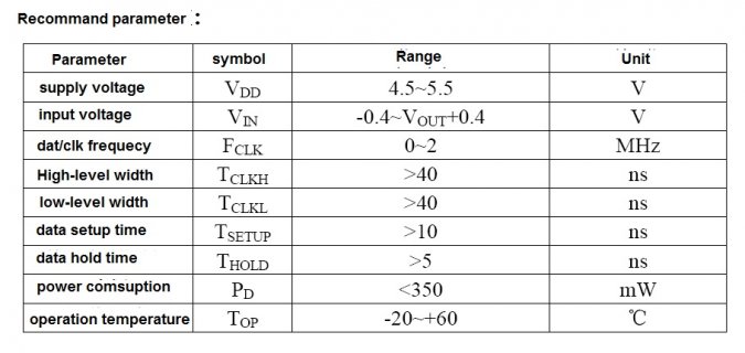
"VCC: Power supply voltage is 3.3-5.5V, recommend an external the 10uF decoupling capacitor." <595's will act erratic in large numbers if you don't decouple near each one. But 10uF is a little large? I use 100nF on 595's.

Recommended Data/clk freq is odd....
LPD8806 Recommended.jpg
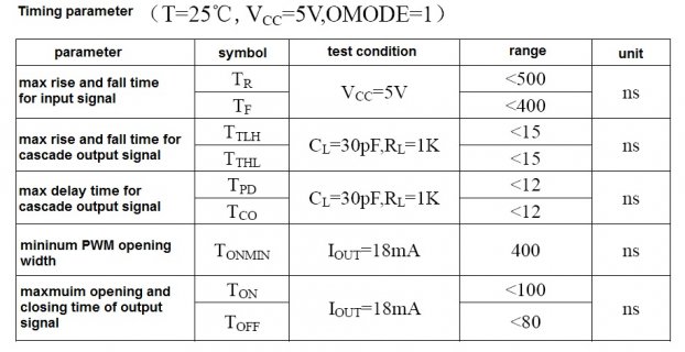
Delay times :)
LPD8806 Time.jpg

Can you swap your LPD8806 Strings and see if that makes it better or worse? You may have a bad chip somewhere.

As a Test Tech I learned to always check the signal first, if its not there or it does not look right then something is wrong.
 
Last edited:
So 5 minutes after I post this I come across a similar thread that answers my dumb question..... If I go down to - void spi_send_bytes(uint8_t *data, int len) and change it to void spi_send_bytes(uint8_t *data, int) ...
WTB a way to kick myself in the arse.


Ok, I dont really want to start yet another thread. So I have reinstalled my dunce cap yet again, I am playing with Ploveday's example and I am setting it up so I can send groups of data.

As you can see below I have been trimming the fat to suit my needs. Atm I just want it to send predefined data so I can look at the timing on my OpenBench Logic Sniffer, I dont need a CS pin for this since it will be talking to TLC5940's and they don't use CS like most SPI devices. I just want to make sure I can reach 24MHz.
The errors are.

SPI_WIP.ino:25:40: error: expected ',' or '...' before numeric constant
SPI_WIP.ino:105:40: error: expected ',' or '...' before numeric constant

Line 25 and 105 are just after uint8_t gsData, and void spi_send_bytes. So I assume its something I did, or didn't do.

If I comment out void spi_send_bytes and whats in my loop it compiles...

I think I will create a special lighted dunce cap just for these occasions.

Code:
//////////////////////////////////////////////////////////
//Code example provided by Ploveday at PJRC forums.

//////////////////////////////////////////////////////////


#include <SPI.h>

#define TLC5940_N 1
#define SPI_SR_TXCTR 0x0000f000
#define len 24
//Define SPI clock speed:
#define BAUD_DIV 0 /* 24MHz SPI */
//#define BAUD_DIV 1 /* 12MHz SPI */
//#define BAUD_DIV 2 /* 8MHz SPI */
//#define BAUD_DIV 3 /* 6MHz SPI */
//#define BAUD_DIV 4 /* 3MHz SPI */

//Globals/members:
uint32_t ctar0, ctar1, mcr;

uint8_t gsData[24 * TLC5940_N] = {
	0b00000000,
	0b00000000,
	0b00000000,
	0b00000000,
	0b00000000,
	0b00000001,
	0b00000000,
	0b00100000,
	0b00000100,
	0b00000000,
	0b10000000,
	0b00010000,
	0b00000010,
	0b00000000,
	0b01000000,
	0b00001000,
	0b00000001,
	0b00000000,
	0b00100000,
	0b00000100,
	0b00000000,
	0b10000000,
	0b00001111,
	0b11111111,
};


void setup(){
//Init code:
  // First set up SPI via library
  SPI.begin();
  SPI.setBitOrder(MSBFIRST);
  SPI.setDataMode(SPI_MODE0);

  // Now reconfigure some stuff
  
  // remember MCR
  mcr = SPI0_MCR;

  // Use both CTARs, one for 8 bit, the other 16 bit
  ctar0 = SPI_CTAR_FMSZ(7) | SPI_CTAR_PBR(0) | SPI_CTAR_BR(BAUD_DIV) | SPI_CTAR_CSSCK(BAUD_DIV) | SPI_CTAR_DBR;
  ctar1 = SPI_CTAR_FMSZ(15) | SPI_CTAR_PBR(0) | SPI_CTAR_BR(BAUD_DIV) | SPI_CTAR_CSSCK(BAUD_DIV) | SPI_CTAR_DBR;

  SPI0_CTAR0 = ctar0;
  SPI0_CTAR1 = ctar1;

//And some macros:

#define SPI_WRITE_8(c) \
	do { \
		while ((SPI0_SR & SPI_SR_TXCTR) >= 0x00004000); \
		SPI0_PUSHR = ((c)&0xff) | SPI0_PUSHR_CTAS(0) | SPI0_PUSHR_CONT; \
	} while(0)


/*
#define SPI_WRITE_16(w) \
	do { \
		while ((SPI0_SR & SPI_SR_TXCTR) >= 0x00004000); \
		SPI0_PUSHR = ((w)&0xffff) | SPI0_PUSHR_CTAS(1) | SPI0_PUSHR_CONT; \
	} while(0)

#define SPI_WAIT() \
	while ((SPI0_SR & SPI_SR_TXCTR) != 0); \
	while (!(SPI0_SR & SPI_SR_TCF)); \
	SPI0_SR |= SPI_SR_TCF;
*/
}

void loop(){

spi_send_bytes(gsData, len);
  
}

void spi_send_bytes(uint8_t *data, int len)
{ 
for (int i=0; i < len; i++)
SPI_WRITE_8(data[i]); 
}
 
Last edited:
Change the name of your len define to something less generic, like MY_LEN or something.

It's conflicting with something in the headers and causing unexpected errors.

Or actually, conflicting with your own code, as you've now noticed. Anyways, change that name :)

- Peter
 
Change the name of your len define to something less generic, like MY_LEN or something.

It's conflicting with something in the headers and causing unexpected errors.

Or actually, conflicting with your own code, as you've now noticed. Anyways, change that name :)

- Peter

Hello Guys,

Is there anywhere the complete lib with the faster SPI support?

Looking around and don't find the SPI.h in this thread
 
The SPI code in the fastspi_led2 library will be usable for just straight SPI work (at least writing) - but i'm still doing tuning work with it. While I've been able to get the SPI output to run at a 24Mhz(ish) clock - irritatingly enough, the SPI subsystem insists on inserting extra delays between transfers, so my real data rate is capped at about 22.5Mbit of data, and attempting to run with the clock set to continuous is a bit of a disaster in the making. However, that's not the library they're referring to up there.
 
The SPI code in the fastspi_led2 library will be usable for just straight SPI work (at least writing) - but i'm still doing tuning work with it. While I've been able to get the SPI output to run at a 24Mhz(ish) clock - irritatingly enough, the SPI subsystem insists on inserting extra delays between transfers, so my real data rate is capped at about 22.5Mbit of data, and attempting to run with the clock set to continuous is a bit of a disaster in the making. However, that's not the library they're referring to up there.

You extracted the SPI-Code from the fastspi_led2? Whats about the Sd2Card library and the Teensy 3.0 Part did you take a look at this?

https://github.com/manitou48/teensy3/blob/master/spiperf.ino
 
Last edited:
No - I didn't extract it, I wrote it. There are spi classes in there that can be used for writing to SPI independently of just writing to LED library (for both hardware ARM and AVR SPI as well as bit-banging emulation (that runs at 4.5Mbit on the teensy 3) if you don't want to use the hardware SPI port - and working on adding DMA support for the teensy 3) - once I finish the LED library i'll see about making it work for generic reading as well. The interfaces need some cleaning up before they get used for general work though.

I don't have anything to do with the sd2card library.

What, specifically, are you looking for?
 
Right, but more specifically - are you just looking for something to write data out over SPI as quickly as possible? Are you looking for something that can read as well?

Right now the SPI class in my library is focused on writing SPI data, but not reading, also it's tuned to the led strips that my library works with - there may be things that I need to do to make it a bit more generically useful, but without some more details I can't tell whether or not what I have now would be useful for you.
 
I just did some tests and got a max serial transfer rate of 1843200. I got to this number by doing 115200 *2 *2 *2 *2 =1843200. I don't know that this is the scientific way of testing it, but I was able to get reliable communication between 2 teensy3.0's using the SerialHandler library I used for arduino a while back.

Here's my issue, and maybe someone can point me in a better direction:
I am using two sets of (teensy 3.0 to control a stepper driver), and a third teensy3 to be the master controller. I am pulsing the stepper drivers on inturrupts every 75uSec, so I wanted to achieve speeds fast enough to sneak in transmissions between pulses. I know my SerialHandler is adding a few extra bytes to each transmission, but I don't know enough about checksums to do my communication without it, although I am looking into it.

Will interrupts hurt my serial transmissions, or am I just worrying too much about this? And does Serial2 & Serial3 not transfer as fast as Serial1? I would really love to work with SPI and get these super fast speeds, but I would need to send from one teensy and READ from the other. Any ideas?
 
Last edited:
I've considered writing a high performance SPI library. But at this point, there's 3 major problems.

1: It would depend on collaborating with others to support non-Teensy boards like Due and Maple.

I tried to test our OSC library on maple but their IDE is just too old (no stream class). It looks like they are just going to fade out because they don't have
the resources to move libraries and stay up on the latest IDE versions.
For me the board to watch is the Fubarino Mini. It has much in common performance wise with the Teensy 3 and an interesting
capacitance sensing scheme.
 
Rick Anderson gave me a Fubarino Mini this weekend at Maker Faire. I tested it for the first time today. It is indeed fast, almost as fast as Teensy 3.0 with the Serial.available() & Serial.read() test. However, it too lacks the Arduino Stream class, so no Serial.readBytes().
 
The problem with the Maple is that the creators aren't really doing much with it, they have put all their new boards on permanent hold. The current maple has tons of power including 2 SPI with DMA, but nobody is really working on it. I considered asking the same questions there as I have here, and in other posts I have going but I fear they will go in about the same direction as here, nowhere.

There current chip has STM32F103.
Serial peripheral interface (SPI)
Up to two SPIs are able to communicate up to 18 Mbits/s in slave and master modes in fullduplex
and simplex communication modes. The 3-bit prescaler gives 8 master mode
frequencies and the frame is configurable to 8 bits or 16 bits. The hardware CRC
generation/verification supports basic SD Card/MMC modes.
Both SPIs can be served by the DMA controller.

They where working on a STM32F407 but stopped I believe.
Serial peripheral interface (SPI)
The STM32F40x feature up to three SPIs in slave and master modes in full-duplex and
simplex communication modes. SPI1 can communicate at up to 37.5 Mbits/s, SPI2 and
SPI3 can communicate at up to 21 Mbit/s. The 3-bit prescaler gives 8 master mode
frequencies and the frame is configurable to 8 bits or 16 bits. The hardware CRC
generation/verification supports basic SD Card/MMC modes. All SPIs can be served by the
DMA controller.
The SPI interface can be configured to operate in TI mode for communications in master
mode and slave mode.

I drooled, and then noticed that nobody had done anything in weeks/months..... :(
 
Last edited:
Rick Anderson gave me a Fubarino Mini this weekend at Maker Faire. I tested it for the first time today. It is indeed fast, almost as fast as Teensy 3.0 with the Serial.available() & Serial.read() test. However, it too lacks the Arduino Stream class, so no Serial.readBytes().

Yes, at least MPIDE 23 has a stream.h (Maple doesn't) but it is not the Arduino one with the block readBytes() as you note.
I am optimistic that by the end of the year all the major forked IDE's for variants will synchronize to 1.5. Some of the cases are really easy to do
such as Flora.
 
I am optimistic that by the end of the year all the major forked IDE's for variants will synchronize to 1.5.

Really?

MPIDE might, since Rick and Mark wrote much of the "platforms" code that became Arduino 1.5.x. But I had a conversation with Rick at Maker Faire. Among several topics, he talked about porting newer Arduino code into MPIDE (which appears to be mostly based on Arduino 0023). He never mentioned a package for 1.5.x.

The many clones that are only AVR chips using the Arduino core (with little or no customization) are likely to support 1.5.x. It's really made for them.

I plan to start supporting it at 1.5.3. It's probably going to be a lot of work, so I'm really not looking forward to it...

I really doubt others will support 1.5.x as an add-on. Completely forking is simply a lot easier. Most people take the easiest path.

The both way path that Arduino walk at the moment make me tiered. There is 1.5.x for the Due mostly and 1.0.x for Teensy and other Arduino-Stuff or Arduino-like. It's one thing to have 2 folders for hardwarespecific librarys but 4 or more with both IDE's and the Teensy it's hard to find the librarys where I lost it. 1.5.x is still beta but works good for me. Btw. I don't think they make there work easyer with porting in every way from 1.0 to 1.5 and back.
 
Last edited:
Litlle help please

Donziboy, where did you get these numbers from? I've been looking at the datasheet, but I still don't understand the correlation between
0x000f000 and 0x0004000.

Can you explain how you determined 0x0000f000
Code:
#define SPI_SR_TXCTR 0x0000f000


and how you got 0x00004000
Code:
#define SPI_WRITE_8(c) \
	do { \
		while ((SPI0_SR & SPI_SR_TXCTR) >= 0x00004000); \
		SPI0_PUSHR = ((c)&0xff) | SPI0_PUSHR_CTAS(0) | SPI0_PUSHR_CONT; \
	} while(0)
 
Last edited:
Really?

MPIDE might, since Rick and Mark wrote much of the "platforms" code that became Arduino 1.5.x. But I had a conversation with Rick at Maker Faire. Among several topics, he talked about porting newer Arduino code into MPIDE (which appears to be mostly based on Arduino 0023). He never mentioned a package for 1.5.x.

The many clones that are only AVR chips using the Arduino core (with little or no customization) are likely to support 1.5.x. It's really made for them.

I plan to start supporting it at 1.5.3. It's probably going to be a lot of work, so I'm really not looking forward to it...

I really doubt others will support 1.5.x as an add-on. Completely forking is simply a lot easier. Most people take the easiest path.

Yes, in fact after finishing that first release of OSC for Arduino, I switched to working on what is needed to support Fubarino MINI. There is enough of a stream.h to do what the OSC SLIP library needs. However there are some surprises in MPIDE that make me nervous. For example, I like to read all the analog inputs on a platform by a call to analogRead() enumerating the channel number from 0,1,2,3 until the number of analog inputs. They seem to have interpreted things so that you have to pass in A0, A1, A2 etc which are symbolic and I can't enumerate:
Code:
int analogRead(uint8_t pin)
{
	int analogValue;
	uint8_t	channelNumber;
	uint8_t ain;

	/* Check if pin number is in valid range.
	*/
	if (pin >= NUM_DIGITAL_PINS_EXTENDED)
	{
		return 0;
	}
	/* Pin number is allowed to be either the digital pin number or the
	** analog pin number. Map the input so that it is guaranteed to be
	** an analog pin number.
	*/
	ain = (pin < NUM_DIGITAL_PINS) ? digitalPinToAnalog(pin) : NOT_ANALOG_PIN;
	if (ain == NOT_ANALOG_PIN) {
		return 0;
	}

Fubarino MINI has little to offer for most applications over the Teensy 3.0 - just a few easier to reach pins. However
the PIC32 capacitance sensing module is more flexible and can do unusual things like time to digital conversion.
 
Last edited:
Status
Not open for further replies.
Back
Top