Teensy 3.0 - driving an SSD1289 with utft

Status
Not open for further replies.
Something I just remembered. In that library I posted. all controllers other than SSD1289's are disabled. if you try it and have something other than a SSD1289, you'll have to edit memorysaver.h and comment out the appropriate disables.
 
Thankyou Qumefox for posting your changes - I've merged the new functions into HW_Teensy3.h, and restructured it a bit to make it *much* easier for people to move the pins. The pins are now defines at the beginning of the file, so you can edit them to whatever pins you'd rather use (both yours and mine are there by default). I didn't want to use 0-15 myself because it conflicts with the hardware SPI pins, and the underside pads are awkward to use so I can understand others not wanting to use them, so I thought brining it out to an initial block of defines would let people change them around as desired.

My updated HW_Teensy3.h is at http://www.dawnmist.net/arduino/HW_Teensy3.h (and my full UTFT lib at http://www.dawnmist.net/arduino/UTFT_2.0.1.zip - note that this has 1 extra function "invertColors" to swap foreground/background colours over since I use that *very* heavily).
 
I only used 1-15 for simplicity's sake to get the display working. When I actually start my project, they won't be using those particular pins.

Also, do you think there are any performance improvements to be had in converting to direct register addressing instead of digitalWriteFast() for each pin?

I'm guessing there probably are, but I'm not really sure how. My best guess would be to use port D for 8-bit or the high-byte of 16 bit, and split the low byte of 16 bit in two and use port B. Port C has the SPI pins smack in the middle of it, so it's more awkward. From the tutorial linked earlier:

Teensy-3 Pin, GPIO Port, GPIO Bit #
---------------
16 B 0
17 B 1
19 B 2
18 B 3

0 B 16
1 B 17
32 B 18
25 B 19

2 D 0
14 D 1
7 D 2
8 D 3
6 D 4
20 D 5
21 D 6
5 D 7

Mind you, I'm currently having issues using pin 20 - I suspect it's because it's been initialised for SPI and I need to do something to turn it back into a normal pin...
 
A pinMode(20,OUTPUT) should fix it. However i'm not sure where the best place to add it would be since it's set in the UTFT teensy hardware define already.. Is the SPI library getting initialized later and overwriting it?

Also, have you had issues with UTFT's drawRect function not drawing complete rectangles? Mine seems to be leaving out a pixel in one corner.
 
Last edited:
For the drawRect function...yes, it does seem to be missing the bottom left corner pixel. I hadn't noticed that until you pointed it out.

For the pinMode...I was looking at the UTouch library. That sets pinMode when you select the pin (and I was attempting to use pin 20 for CS for it), but when the wire was connected to the teensy, it couldn't be recognised by Windows at all. Teensy wasn't starting, I wasn't able to force to load to bootloader (holding the reset button down while plugging in), etc. I've just retried it, and it's worked fine this time. It gave me a fright the first time though, because I thought I'd bricked my teensy. Good news is the UTouch library works without modification so far...at least on the non-spi pins. I had trouble trying to use the spi interface for them when I first tried...but given that the issues I had with pin 20 are gone I think I should retry them ;). (I wasn't getting any data back from the data read when I first tried it - it detected a touch, but the co-ordinates were always 0,0). Note: I'm also using SdFat, so it's possible that it's set up the SPI in a way that doesn't work very well with the touch controller chip.
 
Last edited:
I haven't really delved into much else other than just getting the display working yet, though the touchscreen is next on my list, once I bring out the bottom pads on the teensy so I can free up the SPI pins
 
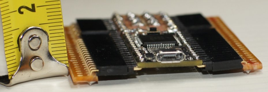
I've got wires soldered to those pads underneath and brought out to pins that I've then breadboarded

What specification cable did you use to solder to the pads underneath? it looks like it worked out quite well for you.

I am really interested in what diameter the cable you used was and whether it was single core or stranded and also if you would recommend it?

Thanks
Ex.
 
It really shouldn't matter for the lengths involved. Wire size should only matter in two situations. Long wiring runs, or dealing with significant amounts of current. The latter is mostly irrelevant, since the teensy itself isn't capable of sourcing significant amounts of current, and shouldn't be used as such. For most projects, wire length isn't going to be an issue either, since most sensors, displays, etc, are going to be within six inches of the teensy anyway. For general purpose use, I probably wouldn't go below 26 gauge, but like I said, it's not that critical and most likely anything you have laying round will be larger than that, which is fine.
 
It really shouldn't matter for the lengths involved. Wire size should only matter in two situations. Long wiring runs, or dealing with significant amounts of current. The latter is mostly irrelevant, since the teensy itself isn't capable of sourcing significant amounts of current, and shouldn't be used as such. For most projects, wire length isn't going to be an issue either, since most sensors, displays, etc, are going to be within six inches of the teensy anyway. For general purpose use, I probably wouldn't go below 26 gauge, but like I said, it's not that critical and most likely anything you have laying round will be larger than that, which is fine.

Thanks for the response, really I was just interested in the diameter and whether single core or stranded just because it looked like the diameter used had worked well in the space available. I understand the electrical/electronic characteristics side of things but I realise I had not pointed this out. I have actually used the cores from a CAT 5 network cable and they were exactly what I needed size wise. i will post some pics in due course, not pretty but functional :)
 
Now to my current question. Received my TFT displays and I am now trying to get them going with little success in the first couple of hours. This is a question for Dawnmist and Qumefiox really, what model are you using in UTFT for the TFT display with the SSD1289?

As far as I can see there are 4 options:

ITDB32S
TFT01_32
INFINIT32
GEE32

I have checkd and rechecked my connections and cannot find a fault but still no joy.

I currently have the same wiring as Qumefox i.e. DB0 to pin 0 upto DB15 to pin 15 with RS/WR/CS/RST to pins 20,21 22 & 23 respectively.

The code I am trying at present:

Code:
#include <UTFT.h>

// Declare which fonts we will be using
extern uint8_t SmallFont[];

//UTFT myGLCD(ITDB24E_16,38,39,40,41);   // Remember to change the model parameter to suit your display module!
// Parameters:
//	Model
//	RS (register Select)
//	WR (Write)
//	CS (Chip Select)
//	RST (Reset)
UTFT myGLCD(ITDB32S, 20, 21, 22, 23);   // Remember to change the model parameter to suit your display module!
//UTFT myGLCD(TFT01_32, 20, 21, 22, 23);   // Remember to change the model parameter to suit your display module!
//UTFT myGLCD(INFINIT32, 20, 21, 22, 23);   // Remember to change the model parameter to suit your display module!
//UTFT myGLCD(GEEE32, 20, 21, 22, 23);   // Remember to change the model parameter to suit your display module!

void setup()
{
	// Setup the LCD
	myGLCD.InitLCD();
	delay(2000);
	myGLCD.setFont(SmallFont);
	// Clear the screen and draw the frame
	myGLCD.clrScr();

	myGLCD.setColor(255, 0, 0);
	myGLCD.fillRect(0, 0, 319, 13);
}

void loop()
{
}

As you can see from the commented out code I have tried different models but still no luck.

I also have the latest library uploaded by Dawnmist (Thanks :) ) V2.0.1 and have the correct pin defines from that as far as I can tell

Code:
/* Set your pins here
 * For 8-bit data bus, pins DB_8 to DB_15 are used.
 *
 * To use pins 0-7 and the pads underneath the Teensy 25-32, change the
 * "if 0" below to "if 1".
 */
#if 0
	#pragma message("Using pins 0-7 and 25-32")
	#define DB_0 25
	#define DB_1 26
	#define DB_2 27
	#define DB_3 28
	#define DB_4 29
	#define DB_5 30
	#define DB_6 31
	#define DB_7 32
	#define DB_8 0
	#define DB_9 1
	#define DB_10 2
	#define DB_11 3
	#define DB_12 4
	#define DB_13 5
	#define DB_14 6
	#define DB_15 7
#else
	#pragma message("Using pins 0-15")
	#define DB_0 0
	#define DB_1 1
	#define DB_2 2
	#define DB_3 3
	#define DB_4 4
	#define DB_5 5
	#define DB_6 6
	#define DB_7 7
	#define DB_8 8
	#define DB_9 9
	#define DB_10 10
	#define DB_11 11
	#define DB_12 12
	#define DB_13 13
	#define DB_14 14
	#define DB_15 15
#endif

I do also get the confirming message during compile time "HW_Teensy3.h : Using pins 0-15"

If you can spot any stupid mistakes or can think of anything I can try please let me know.

I am compiling with CPU speed of 24 MHz

Thanks
Ex.
 
There is a model name "SSD1289" (as per page 3 of the supported displays pdf included in the library's files).

My initialization is:
Code:
uint8_t lcdRS = 19;  // Register Select
uint8_t lcdWR = 18; // Write
//uint8_t lcdRD;       // Read - Unused
uint8_t lcdCS = 17;  // Chip Select
uint8_t lcdReset = 24;  // Reset

UTFT screen(SSD1289, lcdRS, lcdWR, lcdCS, lcdReset);
and then everything else matches what you've got above.

Other things to check:
1. Is the screen's backlight connected to power? I've usually had it connected to an analogue pin on the teensy so I could control it, but it needs to be given ~3.3v power for full brightness.
2. Check the data pin connection order carefully - make sure you haven't reversed/inverted it by mistake.

Which particular screen did you get? Any links to the screen's specs? Photo of the wiring connections?
 
Anyone having issues using setColor(?, 0, 0); ?? it seems red is having issues at least on my 32WD tft. I can fade in blue and yellow no problem, but when I try red.... it seems the values are not working correctly on red.

Code:
  while(1){
    readB(r, b);
    if (hDir == 0){
      hCount+=10;
      setColor(0, hCount, 0);
      if (hCount == 250)
        hDir = 1;
    }
    else if(hDir == 1){
      hCount-=10;
      setColor(0, hCount, 0);
      if (hCount == 0)
        hDir = 0;
    }
    print("Begin", CENTER, 120);
    if(rState == LOW || bState == LOW){
      setColor(0, 0, 0);
      print("Begin", CENTER, 120);
      break;
    }
  }

the above works fine for fading yellow on and off on text, however the second I try to use red I get erratic on and offs. Example would be (60,0,0) is moderately on however (130,0,0) is damn near off on my screen.
 
Now to my current question. Received my TFT displays and I am now trying to get them going with little success in the first couple of hours. This is a question for Dawnmist and Qumefiox really, what model are you using in UTFT for the TFT display with the SSD1289?

As far as I can see there are 4 options:

ITDB32S
TFT01_32
INFINIT32
GEE32

It's none of those. if your display is a SSD1289, it should be defined as a SSD1289 to UTFT. The interface IC name is what get's passed to UTFT, not the lcd model. As dawnmist said, the line should read something like:

UTFT myGLCD(SSD1289,20,21,22,23);

Anyone having issues using setColor(?, 0, 0); ?? it seems red is having issues at least on my 32WD tft. I can fade in blue and yellow no problem, but when I try red.... it seems the values are not working correctly on red.

the above works fine for fading yellow on and off on text, however the second I try to use red I get erratic on and offs. Example would be (60,0,0) is moderately on however (130,0,0) is damn near off on my screen.

I haven't done much since my last pokings at mine, but it's still hooked up here on the desk. I'll poke around at it tomorrow after work and see how it behaves. Right now, it's 2am. I'm going to bed. heh.
 
Last edited:
There is a model name "SSD1289" (as per page 3 of the supported displays pdf included in the library's files).

My initialization is:
Code:
uint8_t lcdRS = 19;  // Register Select
uint8_t lcdWR = 18; // Write
//uint8_t lcdRD;       // Read - Unused
uint8_t lcdCS = 17;  // Chip Select
uint8_t lcdReset = 24;  // Reset

UTFT screen(SSD1289, lcdRS, lcdWR, lcdCS, lcdReset);
and then everything else matches what you've got above.

Other things to check:
1. Is the screen's backlight connected to power? I've usually had it connected to an analogue pin on the teensy so I could control it, but it needs to be given ~3.3v power for full brightness.
2. Check the data pin connection order carefully - make sure you haven't reversed/inverted it by mistake.

Which particular screen did you get? Any links to the screen's specs? Photo of the wiring connections?

Okay, so I changed to SSD1289, triple checked the wiring and had some very short lived results when I put a delay before the initialisation. It seemed as if the code was running before the TFT was ready and then it also seemed to be updating quicker than it could handle with similar effects as seen by Qumefox before the rewire. I did at least see my square on the display. I have used a multi meter to check all connections from TFT to Teensy, I think I know the pin numbering by heart now! I am going to have another go in a minute and check once more.

One thought I had was contrast. When working with a 2 line LCD I could not see a thing before adjusting the contrast but it was working fine. Is there any kind of contrast adjustment on these displays you know of?

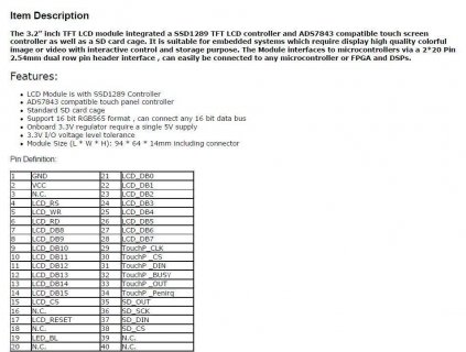
Regarding which screen I have 2 different models but both essentially use the exact same connections even though one of them has them numbered differently. Backlight is connected by the way

I have two with icons and two without. I bought them from eBay but here is a link to the model with icons:

http://www.uctronics.com/32inch-tft-lcd-module-with-touch-panel-sd-card-cage-p-171.html?currency=GBP

I have embedded a jpg of the detail of the one without. The actual physical connections are identical but they are numbered differently. Well 21 to 40 are identical on both but 0-20 on one maps to 20 to 0 on the other. I know this sounds confusing but the same physical pin is labelled 1 on one unit and 20 on the other but the pin function is the same so really the only difference is the silk screen on the PCB.

I have checked all pin connections for the Teensy and breakout using this simple dirty code and a LED and resistor on a flying lead ( I know it is lazy and dirty :) ):

Code:
	int pins[34];

	void setup()
	{
		for(int i = 0; i < 34; i++)
		{
			pins[i] = i;
			pinMode(pins[i], OUTPUT);
		}
	}

	void loop()
	{
		// Normal Pins, set HIGH
		for(int i = 0; i < 2; i++)
		{
			digitalWrite(pins[i], HIGH);
		}
		for(int i = 7; i < 9; i++)
		{
			digitalWrite(pins[i], HIGH);
		}
		for(int i = 11; i < 20; i++)
		{
			digitalWrite(pins[i], HIGH);
		}
		for(int i = 24; i < 34; i++)
		{
			digitalWrite(pins[i], HIGH);
		}

		// PWM Pins, ramp up
		for(int i = 0; i < 256; i++)
		{
			analogWrite(pins[3], i);
			analogWrite(pins[4], i);
			analogWrite(pins[5], i);
			analogWrite(pins[6], i);
			analogWrite(pins[9], i);
			analogWrite(pins[10], i);
			analogWrite(pins[20], i);
			analogWrite(pins[21], i);
			analogWrite(pins[22], i);
			analogWrite(pins[23], i);
			delay(2);
		}

		// Normal Pins, set LOW
		for(int i = 0; i < 2; i++)
		{
			digitalWrite(pins[i], LOW);
		}
		for(int i = 7; i < 9; i++)
		{
			digitalWrite(pins[i], LOW);
		}
		for(int i = 11; i < 20; i++)
		{
			digitalWrite(pins[i], LOW);
		}
		for(int i = 24; i < 34; i++)
		{
			digitalWrite(pins[i], LOW);
		}

		// PWM Pins, ramp down
		for(int i = 255; i >= 0; i--)
		{
			analogWrite(pins[3], i);
			analogWrite(pins[4], i);
			analogWrite(pins[5], i);
			analogWrite(pins[6], i);
			analogWrite(pins[9], i);
			analogWrite(pins[10], i);
			analogWrite(pins[20], i);
			analogWrite(pins[21], i);
			analogWrite(pins[22], i);
			analogWrite(pins[23], i);
			delay(2);
		}
	}
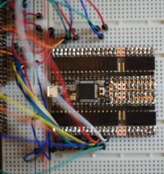
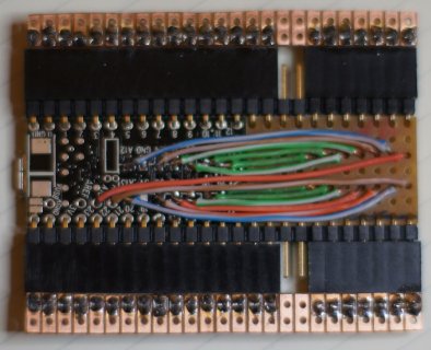
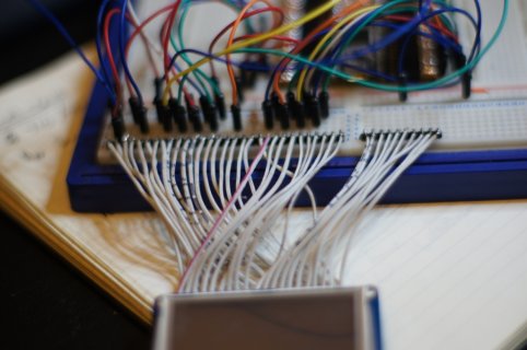
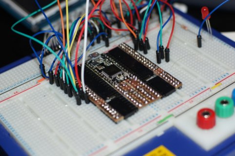
Some pics ( the ones for the TFT breakout may look familiar :) ). I made my own vero board breakout for the underside pins with low profile being my main criteria to fit my project enclosure.

DSC05907.JPGDSC05910.jpgDSC05914.JPGNew Picture.jpgDSC05906.JPGDSC05908.JPG

The soldering isn't pretty but it does the job :)

You mentioned in one of your posts that you fiddled with some write timings early on, do you have any notes you can share? Anyway it is time to play again and hopefully I will get to the bottom of the issue.

Anyway thanks to you and Qumefox for the code and pointers that got me this far :)
 
Got it ! I read someone else had this issue but still missed it. The ground rail on the breadboard is full width but the VCC rail is broken ! All my issues were caused by the LCD_RD pin not being pulled high due to the break in the rail. I am sure I had it in first time round. I obviously got to see some stuff on the display when the pin floated high.

I now have a lot of code to write !

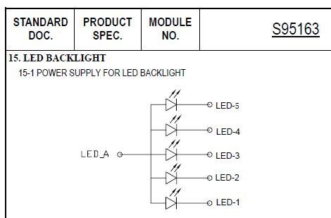
One question though, are you using a resistor when driving the LED backlight from PWM? I currently have a resistor in line but was scared to connect it directly as the diagrams do not show a resistor:

LED Backlight.jpg

Thanks for all your help :)
 
Are you remembering to pull the RD pin on the LCD high?

**edit. nevermind, you beat me to it.**


On the backlight issue. That really depends on what the LCD breakout board (the PCB the LCD is actually attached to) is doing with the LED's. I can't really say for certain because it varies from display to display it seems.. The actual LCD component of all these seems to be the same, however a bunch of different companies are making their own breakout boards with SD card readers, etc. No two i've seen from different manufactures have been the same.

I know the particular one I have actually has a LED driver on it that has a dimming input.
 
Last edited:
Anyone having issues using setColor(?, 0, 0); ?? it seems red is having issues at least on my 32WD tft. I can fade in blue and yellow no problem, but when I try red.... it seems the values are not working correctly on red.

Just tested on mine. This code runs as expected, so I don't think the problem is the setColor() function of the library, at least, not with the UTFT library I have anyway. You might try double checking your wiring again. When I had data bits swapped originally, the red on my display kind of acted similarly to what you're describing. Though I had other issues as well.

Code:
#include <UTFT.h>

extern uint8_t SevenSegNumFont[];

UTFT myGLCD(SSD1289,20,21,22,23);

int red=0;

void setup()
{
  myGLCD.InitLCD();
  myGLCD.setFont(SevenSegNumFont);
  myGLCD.clrScr();
}

void loop()
{ 
 myGLCD.setColor(red,0,0);
 myGLCD.print(red,CENTER,100);
 if(red==255)
 {
   delay(2000);
   myGLCD.clrScr();
   red = 0;
 }
 else
 {
   red = red + 1;
 }
 delay(100);
}
 
Hmm strange... I'll have to double check.. it's weird tho all other colors work fine.. just anytime I fade red it doesn't fade correctly? I mean it's still red, just the level of brightness isn't correct for each level of brightness.
 
Is this on a breadboard? The issue could be an intermittent data line instead of a swapped one as well. The other option is that you have a bad display. Beyond that, I really have no idea. the function seems to work fine in my setup here.
 
I was wondering if someone could help me get my lcd to work. It's a SSD1289, and I've got it hooked up similar to how Q has his, only I skipped pin13 since it's the LED, so it goes 12, 14, 15, 16. I'm using the 2.0 UTFT library, and I went in and changed the pins in HW_Teensy3.h, and made sure to change the model number in the sketch to read:

UTFT myGLCD(SSD1289,21,20,22,23);

because I've got reset on 23, cs on 22, rs on 21, and wr on 20, but I'm still getting nothing but backlight.
 
Hi

The problem I and others have had was forgetting to pull the the RD pin on the LED high (3.3V), it's easy to miss and has exactly the effect you are witnessing. Hope it helps :)
 
Last edited:
Thank you for the fast response!

Does this mean I put a wire between Rd and a pin and set that pin to output and then high? Is there a good place to add this code?
 
Status
Not open for further replies.
Back
Top