low voltage tripping bounce?

Status
Not open for further replies.
Wow. That's an expensive way to make circuit boards! As a student with a limited budget, why not just learn to use Eagle yourself? Yes, Eagle is a terrible program in many ways, but lots of hobbyists learn to use it fairly well. There's lots of tutorials and info online. There are now several low-cost PCB services like OSH Park, iTead, Seeed Studios, which aren't free, but they make this sort of thing much more affordable if you can learn Eagle, as most hobbyists do these days.

About the design, again, I'm afraid I have only bad news. It obviously is not robust enough. You're going to have to change the hardware. The fact you've already spent so much time and money has no influence on the electrons. Only improving circuity is going to fix this project.

Even my prior suggestion may not be enough. From those photos, it appears you're running some of the pins from a Teensy++ 2.0 directly into a lengthy cable, spanning across a car with an ignition system and perhaps other noisy electronics. The cable goes at least to a display and 4 buttons. It appears to have another jack which might allow another cable to plug in?

This thing looks like some sort of tachometer. If so, I would be really cautious about running any cable into the engine area. Certainly you don't want to directly connect any microcontroller pin into that space. Even the ground wire connected to the microcontroller should probably not enter that space. If you're sensing the spark plugs somehow, whatever type sensor you're using will need some way to be isolated from the system or at least not cause a terrible ground loop current.

While I really do want to help you, there's a limit to what I can do... even if you're willing and able to afford to really try stuff. There's also a practical limit to the tech support I can provide. I'd say this thread and probably several emails I've answered are far beyond the normal support for Teensy... which is essentially what I call "get up and running", and perhaps addressing Arduino compatibility issues (which technically aren't Teensy issues, but Teensy does aim for best possible compatibility with all Arduino libraries and programs, so when people discover issues, I try to fix or address them somehow).

I can offer some advice, as can others on this forum. But ultimately, none of that will ever help if you can't revise the hardware to improve its robustness. Again, I'm really sorry this has gone so badly for you, and you've wracked up some debt without a sale-able product to show for it. But only a hardware redesign, probably based one some serious troubleshooting and experimenting with alternate approaches, is going to address these electrical problems. Ultimately it's about electrons in wires.
 
Bracket Time

Paul,
I'm pretty sure that the device is not a tachometer, but a dial-in display board.

I think that Magnethead494 may not realize that not everyone knows about Bracket racing... I only do because of a former life as an NHRA official.
Bracket racing is a type of drag racing, where you race against others based on a narrow bracket of time. It's more about consistency, than flat out acceleration.
You need to cross the finish time as close to your bracket time as possible.

The dial-in display is a digital bracket time display. It takes the place of writing the racer's bracket time on the window with a white shoe-wax marker.
The small SparkFun Serial Display mounts on the dash to allow the time to be set via the toggle switches.
The large LED display goes in the side window and displays the racer's bracket time to the officials & spectators.

None of the cables need to penetrate the firewall into the engine compartment.

MagnetHead,
Do both displays show the noise problem?
I've heard that floating, unused pins on some serial 7-segment displays can cause problems.
 
Last edited:
As Paul said the problems will not be fixed without some hardware changes. The environment this is being used in is "electrically noisy"(EMI, static, etc.).

Given this better description of the environment and seeing the pictures it looks to me like there are a few things missing.

First, what is the power supply input? Is it rock solid voltage input or plain old "12 volt" from the car? If directly from the car I would want a more robust power supply inside the box.

Second, the connection from the board with the switches to the processor is definitely going to act as an antenna. It needs to be shielded and the connect to the Teensy isolated. I would even consider using differential signaling to reduce the chance of noise.

This is all going to add cost and time, but it is the price you pay for not understanding the environment a device is running in. Unfortunately these lessons are usually learned the hard way. It is also the reason the other devices mentioned cost more. They have additional engineering and materials in order to work correctly in a hostile environment.
 
Wow. That's an expensive way to make circuit boards! As a student with a limited budget, why not just learn to use Eagle yourself? Yes, Eagle is a terrible program in many ways, but lots of hobbyists learn to use it fairly well. There's lots of tutorials and info online. There are now several low-cost PCB services like OSH Park, iTead, Seeed Studios, which aren't free, but they make this sort of thing much more affordable if you can learn Eagle, as most hobbyists do these days.

I'm slowly learning it. I've gotten layout and schematicing mostly figured out, but I haven't gotten to the point of generating CNC files yet. When I started this project 1.5 years ago, I didn't know the first thing about it.

About the design, again, I'm afraid I have only bad news. It obviously is not robust enough. You're going to have to change the hardware. The fact you've already spent so much time and money has no influence on the electrons. Only improving circuity is going to fix this project.

Even my prior suggestion may not be enough. From those photos, it appears you're running some of the pins from a Teensy++ 2.0 directly into a lengthy cable, spanning across a car with an ignition system and perhaps other noisy electronics. The cable goes at least to a display and 4 buttons. It appears to have another jack which might allow another cable to plug in?

While I really do want to help you, there's a limit to what I can do... even if you're willing and able to afford to really try stuff. There's also a practical limit to the tech support I can provide. I'd say this thread and probably several emails I've answered are far beyond the normal support for Teensy... which is essentially what I call "get up and running", and perhaps addressing Arduino compatibility issues (which technically aren't Teensy issues, but Teensy does aim for best possible compatibility with all Arduino libraries and programs, so when people discover issues, I try to fix or address them somehow).

I can offer some advice, as can others on this forum. But ultimately, none of that will ever help if you can't revise the hardware to improve its robustness. Again, I'm really sorry this has gone so badly for you, and you've wracked up some debt without a sale-able product to show for it. But only a hardware redesign, probably based one some serious troubleshooting and experimenting with alternate approaches, is going to address these electrical problems. Ultimately it's about electrons in wires.


Paul,
I'm pretty sire that the device is not a tachometer, but a dial-in display board.

I think that Magnethead494 may not realize that not everyone knows about Bracket racing... I only do because of a former life as an NHRA official.
Bracket racing is a type drag race, where you race against others based on a narrow bracket of time. It's more about consistency, than flat out acceleration.
You need to cross the finish time as close to your bracket time as possible.

The dial-in display is a digital bracket time display. It takes the place of writing the racer's bracket time on the window with a white shoe-wax marker.
The small SparkFun Serial Display mounts on the dash to allow the time to be set via the toggle switches.
The large LED display goes in the side window and displays the racer's bracket time to the officials & spectators.

None of the cables need to penetrate the firewall into the engine compartment.

MagnetHead,
Do both displays show the noise problem?
I've heard that floating, unused pins on some serial 7-segment displays can cause problems.

Wozzy, yes that's what it is. After I saw what Biondo's are selling for (O.O) I tried to make them cheaper. So much for that thought. I think Digital Delay is selling a double sided now for upwards of $600 by the time you order custom colors and shipping.

I'm having some issues with the SF unit, but I'm pretty sure several of them derive from the main unit's problems. Since the indicator is a listener only, I'm hoping to narrow it's issues by fixing the main board's issues.

All I have done is door cars so far..the one shown is going on a pipe rack though, and inherently, guess where it mounts- above the distributor (scoop tray mount). That's why I'm going a little more distance to make it robust, if I can. Especially since it's going from a 7 foot cable that I'm already having trouble with, to a 15 foot cable that's going to go in the same loom as the throttle cable. Yea, that's going to be fun.

As Paul said the problems will not be fixed without some hardware changes. The environment this is being used in is "electrically noisy"(EMI, static, etc.).

Given this better description of the environment and seeing the pictures it looks to me like there are a few things missing.

First, what is the power supply input? Is it rock solid voltage input or plain old "12 volt" from the car? If directly from the car I would want a more robust power supply inside the box.

It's 12V in from the car's electrical (can range from 11 volts for an alternator-less car to 18 volts on a 16V system car like ours), goes through C1 (Panasonic EEU-FM1E102, 1000uF FM filtering Cap) and D1 (Fairfield FFP08H60STU, for flyback protection of electric motors), to a 12 volt regulator (Fairfield KA278R12CTU, which attaches directly to the case as a heatsink), then splits into 2 feeds.

1 feed goes to the resistor networks on the digits, then through the LED's to the darlington, the other feed goes to a 5 volt regulator (On Semi MC7805CTG) which then goes to the teensy and the serial 7 indicator.

Second, the connection from the board with the switches to the processor is definitely going to act as an antenna. It needs to be shielded and the connect to the Teensy isolated. I would even consider using differential signaling to reduce the chance of noise.

I am using a shielded RJ-50 cable from Winford Engineering, but I have had no luck in finding a shielded RJ50 jack for use at the 2 ends.

Pin 1 is +5V
Pin 2 is GND
Pin 3 is TX from teensy to serial 7
Pin 4 is pin D1 on teensy (tens switch)
Pin 5 is pin D0 on teensy (one's switch, down)
Pin 6 is pin B5 on teensy (one's switch, up)
Pin 7 is pin B4 on teensy (tenth's switch, up)
Pin 8 is pin B3 on teensy (tenth's switch, down)
Pin 9 is pin F3 on teensy (hundth's switch, up)
Pin 10 is pin B7 on teensy (hundth's switch, down)


This is all going to add cost and time, but it is the price you pay for not understanding the environment a device is running in. Unfortunately these lessons are usually learned the hard way. It is also the reason the other devices mentioned cost more. They have additional engineering and materials in order to work correctly in a hostile environment.

I'm realizing that. It's got me in one hell of a position.
 
Last edited:
Wozzy, indeed I know pretty much nothing about racing. Glad you mentioned this.

Maybe I ought to make a web page or youtube video about projects with long wires and techniques for noise immunity and robustness?
 
Pin 1 is +5V
Pin 2 is GND
Pin 3 is TX from teensy to serial 7
Pin 4 is pin D1 on teensy (tens switch)
Pin 5 is pin D0 on teensy (one's switch, down)
Pin 6 is pin B5 on teensy (one's switch, up)
Pin 7 is pin B4 on teensy (tenth's switch, up)
Pin 8 is pin B3 on teensy (tenth's switch, down)
Pin 9 is pin F3 on teensy (hundth's switch, up)
Pin 10 is pin B7 on teensy (hundth's switch, down)

After leaving the box with the Teensy++, do any of these wires connect to anything that can touch any metal surface in the car? Especially pin 2 is a concern.
 
Wozzy, indeed I know pretty much nothing about racing. Glad you mentioned this.

Maybe I ought to make a web page or youtube video about projects with long wires and techniques for noise immunity and robustness?

I would say that would be a great idea. Many people just don't realize what real world conditions can do to your project that worked perfectly on your desk/workbench. Knowing anything about harsh/noisy environments ahead of time at least gives you a head start in handling what they can throw at you.

It is the these types of harsh environments that caused things as seemingly simple as RS-485 to be created. Not to mention CAN, LIN, etc. for automotive stuff.
 
Magnethead,

So looking all this over, things might not be so bad for you to make modifications.
If your digits on both displays are experiencing uncommanded changes in the presence of EMI, the problem is most likely noise being picked up by the switch wires.
This affords you the opportunity to perform any necessary fixes on a daughter card or even an inline modification.

You mentioned that you are using shielded cable, but not shielded connectors.
As a start, I would try to attach a ground wire to the shield of the RJ-50 cable, which is then grounded to the aluminum display case.
I presume that the display case is fastened to the vehicle frame so it's grounded also.
Most of the time when protecting from EMI, it's best to only ground the one side of the shielding, or you can introduce ground loops.

Do you have access to the problem vehicle, to reliably repeat the error conditions?
If so, then try this first to see if it works.
If not, try grounding both sides of the shielding.
I'd also recommend ringing out the cable, and flexing it vigorously while operating to rule out spurious vibration induced mechanical cable problems.
Most RJ-50 cables are not designed to wighstand a dynamic environment.
If that doesn't work, we can all explore some other possible signal-to-noise ratio reduction and filtering tricks.
 
Last edited:
Wozzy, indeed I know pretty much nothing about racing. Glad you mentioned this.

Maybe I ought to make a web page or youtube video about projects with long wires and techniques for noise immunity and robustness?

That would be great Paul. Probably would have saved me a lot of **** chasing.

After leaving the box with the Teensy++, do any of these wires connect to anything that can touch any metal surface in the car? Especially pin 2 is a concern.

No. The cable is 100% sealed from the display enclosure (aluminum) to the controller enclosure (plastic).

I would say that would be a great idea. Many people just don't realize what real world conditions can do to your project that worked perfectly on your desk/workbench. Knowing anything about harsh/noisy environments ahead of time at least gives you a head start in handling what they can throw at you.

It is the these types of harsh environments that caused things as seemingly simple as RS-485 to be created. Not to mention CAN, LIN, etc. for automotive stuff.

I concur.

Magnethead,

So looking all this over, things might not be so bad for you to make modifications.
If your digits on both displays are experiencing uncommanded changes in the presence of EMI, the problem is most likely noise being picked up by the switch wires.

This is my best guess. I have a scope, but I haven't really learned how to use it effectively yet. A Chinese model from Sparkfun, of course.

This affords you the opportunity to perform any necessary fixes on a daughter card or even an inline modification.

You mentioned that you are using shielded cable, but not shielded connectors.
As a start, I would try to attach a ground wire to the shield of the RJ-50 cable, which is then grounded to the aluminum display case.
I presume that the display case is fastened to the vehicle frame so it's grounded also.
Most of the time when protecting from EMI, it's best to only ground the one side of the shielding, or you can introduce ground loops.

I wouldn't necessarily say it's fastened to the frame, per se`. On a dragster, it's mounted to a scoop bracket, which mounts to the top of the engine, so the only ground it's going to get is going to be an implied ground-by-contact from the mount, to the scoop tray, to the throttle body/carburetor, to the intake manifold, to the block. So I wouldn't say it's at the same [ground] potential as the frame itself, which is almost always hooked directly to the negative battery post. In a door car, it can be mounted damn near anywhere, including to the window directly, so I won't guarantee anything there, either.

Do you have access to the problem vehicle, to reliably repeat the error conditions?
If so, then try this first to see if it works.
If not, try grounding both sides of the shielding.
I'd also recommend ringing out the cable, and flexing it vigorously while operating to rule out spurious vibration induced mechanical cable problems.
Most RJ-50 cables are not designed to wighstand a dynamic environment.
If that doesn't work, we can all explore some other possible signal-to-noise ratio reduction and filtering tricks.

1 potentially problem vehicle is 30 miles away each way (the dragster, which has not been equipped yet for debugging), so no, I don't have easy access. One fleet of 4 (of which 2 have been sent back and 2 not in use) is 5 miles away and I'm welcome at their shop anytime.

Our personal car has not had any huge problems. The only thing I've observed, was when it was noticed that bumping the starter with the engine off, would occasionally cause a number to change. Other than that, our car has shown no issues.

on the 2 cars that are scrolling, the boxes are fine with engine off and ignition on, but with engine running, they scroll. The RJ-50 cable doesn't go anywhere near the ignition system in either vehicle nor ours, so whatever is causing it, it's doing it from at least 3-4 feet from the ignition box.
 
Our personal car has not had any huge problems. The only thing I've observed, was when it was noticed that bumping the starter with the engine off, would occasionally cause a number to change. Other than that, our car has shown no issues.

I would first focus not on fixing the problem, but trying to find ways to make it more reproducible on the car you have. Then you'll have a lowest cost way to investigate the effectiveness of any changes.
 
I would first focus not on fixing the problem, but trying to find ways to make it more reproducible on the car you have. Then you'll have a lowest cost way to investigate the effectiveness of any changes.

We use a completely different ignition and wiring structure than most cars (I'm sure Wozzy can say, some cars, like ours, are delicately wired to the NHRA specification, with all wires loomed and identified....some, like the one I'm dealing with, look like rats nests...but it works, so they don't want to re-wire to make a device work.). The funny thing is that the ignitions out there are analog technology from the late 90's, and ours is 100% digital (at 4x the cost). Which is funny, because the digital ones are said to emit more EMI than the analog ones are. We have both cylinder heads grounded (via bolt) to the firewall at a seperate point for each with #10 wire, then both of those are connected with #10 wire, a #8 from those 2 lugs to a third lug (welded to the chassis) at the power distribution center in the passenger footwell, and a #8 from there to a fourth grounding point in the truck (lug welded to chassis), which has a 1 ft long #00 welding cable from it to the negative battery terminal. There is also a #00 going from the engine block to the frame rail.

The starter grounds through the block, and when bumping the starter, the number will change when you let go of the button. But if you hold the button (as to actually start the engine), it doesn't affect the box. That's why I thought it may be a low voltage issue, but i now realize it could also be related to a very quick inductive build-up-then-release of the starter motor, and perhaps it's getting around the flyback diode D1 and FM filter C1 and raising the "ground" potential voltage to some other voltage. But that wouldn't fully explain why the other cars are having similar issues, as they are not running an inductive ignition, but a capacitive one. On an MSD, a large capacitor (I will look up a value after dinner) is discharged every 1/(rpm/60) of a second, which feeds the coil's primary coil, induces a charge in the secondary coil, which then fires the spark plug (Which is grounded via the cylinder head) as the distributor's rotor closes the gap from secondary coil to spark plug.
 
Here is the manual for the box that is used in many of the other cars:

http://www.msdignition.com/WorkArea/DownloadAsset.aspx?id=15032387238

"The MSD Ignition features a capacitor which is quickly charged (within one millisecond) with 460 - 480 volts and stores it until the ignition is triggered. With the CD design, the voltage sent to the coil is always at full power even at high rpm."

Their coil: http://www.msdignition.com/WorkArea/DownloadAsset.aspx?id=15032386217

Spec'd as 45,000V @ 140mA max output

Here is the manual for the box we use:

http://www.msdignition.com/WorkArea/DownloadAsset.aspx?id=15032386180

It puts out 535 volts to the primary terminals.

Our coil: http://www.msdignition.com/WorkArea/DownloadAsset.aspx?id=15032386246

45,000V @ 2.0 amps.
 
All of the electrical is in the passenger footwell, the box is in the driver sail window, controller is on the front halo bar. (That's me in the red shirt)

20121222_204847.jpg


859001_424269624325453_60425544_o.jpg
 
Last edited:
I did get some prelim screenshots of the boards, not sure how much they will help (A significant amount was changed from these to the finals):

Screenshot2012-12-27at92926PM.png


Screenshot2012-12-27at92840PM.png
 
what would be the best way to ground the RJ50 cable? it still has to be plugged/unplugged from the circuit board on both ends if needed, but i can't find any shielded RJ50 connectors.
 
Is any of the shielding exposed at the connector?
If so you can probably just use alligator clips for the sake of testing.
Typically the shield is a thin sheet metal frame surrounding the plastic insulator.

If not, you may need to perform surgery on the cable jacket to expose the shielding and solder a pigtail that you can ground with a lug.
 
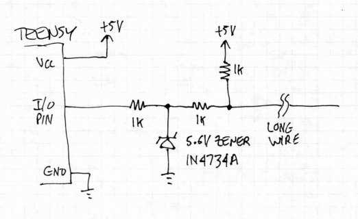
If you redesign the board, as an absolute minimum level of protection against destroying the Teensy++, I would recommend add 3 resistors and 1 zener diode for each pushbutton signal.

pin.jpg
(click for larger image)

It is a lot of parts, but they're very cheap. You can buy the resistors in 4 or 8 packages, which actually costs slightly more in parts but tends to reduce the cost of assembling the board.

From the signal working backward to the Teensy pin, the first 1K resistor acts as the pullup so you get a logic high when the button is not pressed. A 1K resistor is much lower impedance than the internal pullup, so hopefully it will help with lessening the ability to pick up noise. You could change this to 470 or even 100 ohms if you still get false signals. The other 3 parts don't help with noise at all, but will protect the Teensy from damage. If a voltage spike is induced on to coupled to the line, anything over 5.6 or under -0.7 volts will appear across the 1K resistor. Current will flow through the zener diode, but that 1K resistor will limit the current to a relatively low number of mA. 1 watt zener diodes are able to take pretty substantial short duration current, so it should be very rugged. Zeners aren't perfect... the voltage might be 6 or -1 volts momentarily during a spike. The Teensy++ also has some protection diodes built in, but they're much less capable than the zener. The other 1K resistor helps limit the current into the Teensy++, so whatever portion of a horrible spike remains after the zener will be limited in how much current can flow to the Teensy's protection diodes. This 2-level protection should give you a very rugged product, using resistors and diodes that cost only pennies. I labeled all the resistors 1K, which is easiest so you only need to buy a single value. If you really want to be extra cautious, you could increase the resistor between the diode and the Teensy to 10K or even 47K (but be sure the internal pullup is not in use).

You might also consider adding a capacitor in parallel with the zener diode. That may help suppress noise, if it's very rapid spikes. If you do a new board layout, I'd suggest adding a space on the board for those caps, and later you can decide if they're necessary and if so, what value works best. 0.1 uF is probably about right. Larger values will suppress more noise, as long as they're still a high-frequency ceramic or poly capacitor, but more capacitance slows the response speed. A 0.1 uF capacitor and the two 1K resistors will still respond within 1ms, which is plenty fast enough for buttons pressed by humans.
 
If you redesign the board, as an absolute minimum level of protection against destroying the Teensy++, I would recommend add 3 resistors and 1 zener diode for each pushbutton signal.

View attachment 324
(click for larger image)

It is a lot of parts, but they're very cheap. You can buy the resistors in 4 or 8 packages, which actually costs slightly more in parts but tends to reduce the cost of assembling the board.

From the signal working backward to the Teensy pin, the first 1K resistor acts as the pullup so you get a logic high when the button is not pressed. A 1K resistor is much lower impedance than the internal pullup, so hopefully it will help with lessening the ability to pick up noise. You could change this to 470 or even 100 ohms if you still get false signals. The other 3 parts don't help with noise at all, but will protect the Teensy from damage. If a voltage spike is induced on to coupled to the line, anything over 5.6 or under -0.7 volts will appear across the 1K resistor. Current will flow through the zener diode, but that 1K resistor will limit the current to a relatively low number of mA. 1 watt zener diodes are able to take pretty substantial short duration current, so it should be very rugged. Zeners aren't perfect... the voltage might be 6 or -1 volts momentarily during a spike. The Teensy++ also has some protection diodes built in, but they're much less capable than the zener. The other 1K resistor helps limit the current into the Teensy++, so whatever portion of a horrible spike remains after the zener will be limited in how much current can flow to the Teensy's protection diodes. This 2-level protection should give you a very rugged product, using resistors and diodes that cost only pennies. I labeled all the resistors 1K, which is easiest so you only need to buy a single value. If you really want to be extra cautious, you could increase the resistor between the diode and the Teensy to 10K or even 47K (but be sure the internal pullup is not in use).

You might also consider adding a capacitor in parallel with the zener diode. That may help suppress noise, if it's very rapid spikes. If you do a new board layout, I'd suggest adding a space on the board for those caps, and later you can decide if they're necessary and if so, what value works best. 0.1 uF is probably about right. Larger values will suppress more noise, as long as they're still a high-frequency ceramic or poly capacitor, but more capacitance slows the response speed. A 0.1 uF capacitor and the two 1K resistors will still respond within 1ms, which is plenty fast enough for buttons pressed by humans.

Thanks Paul, I will definitely keep that in mind. I haven't had a chance to do much testing (still dealing with homework), but I can try using alligator clips to ground the shield. I haven't really figured out how to use the scope I have, but what would be the best way to look at the noise itself? To hook the lead to the electrical ground where the unit plugs in, and connect the lead's ground to the battery post? Or put the lead and ground across the power supply wires (+12 and gnd)? I can record the display for analysis here.

As I mentioned before, the box I took pictures of will be going right over the distributor, but the ignition and battery are all in front. So if there's going to be noise, it will be very prevalent. The coil's primary wires and the power and data cables for the box will all be in close proximity (but not loomed together).
 
Last edited:
Paul, what is the functional difference between INPUT with the pin written HIGH, and INPUT_PULLUP? I am currently using the former, would the latter do anything different functionally?

I contacted a person that does on board computers for racing, and he said he can help a little bit, but not very much. I'm compiling a system schematic right now.
 
Randy,

Here is the schematic...the lines are thin so I had to do it at a really high resolution.

I tried SPI originally using shift registers and rotational shaft encoders, but with no way for error checking, the ignition's noise just tore the bitstream apart. Some cars it worked fine, some it was just garbled segment patterns.

I tried again using darlingtons and individual switches, and the display itself works fine, but the signal is getting scrambled between the display housing and the controller. With the engine off is fine, but with it running, the numbers will scroll up/down randomly, like the switches are being pressed.

I have the microcontroller's pins set to a logic high, and when the switch is pressed, the pin will go low, triggering a process to change the number. So what is happening, is that somewhere, those logic lines are falling and representing a low rather than a high. But I am not sure how to dissect the noise issue, so I am taking my oscilloscope to one of the cars that is not working right, so that I can see what the noise looks like.

It may be something as simple as the internal pull-up resistors not being strong enough to hold a logic HIGH across a length of cable, or it could be something as complex as the ignition's noise changing the actual potential of ground from 0 volts to an arbitrary value.

I remember when we had the MSD 7-3 red box, our voltage in the DL box showed 16.x volts on a 12 volt system, and with the digital 7 pro-mod box and 32,000uF MSD capacitor (which we have unhooked just to prove it's not a factor in testing), it shows the true 17-18 volts of the 16 volt system. I don't know if that type of discrepancy could be causing issues with what I have going, but I am definitely keeping it in mind.

And yes, ours is purple.

Thanks,
Steve

dial-board-system.jpg


20121222_204847.jpg


859001_424269624325453_60425544_o.jpg
 
Last edited:
If you do not have external pullups on your (button?) inputs, then you should definitely be using INPUT_PULLUP.

Though if you're running it over long cables, external stronger pullups may be advisable.

- Peter
 
Status
Not open for further replies.
Back
Top