New I2C library for Teensy3

I got it to work! Seems using an I2C_NOSTOP for the Wire.endTransmission was the trick. See below.


Wire.beginTransmission(dev);// + 0x60); // slave addr
Wire.write(0x02); // command, read
Wire.write(address); // start address
Wire.write(0x00); // address step
Wire.write(0x01); // number of reads requested
success = Wire.endTransmission(I2C_NOSTOP, 100);
Serial.print("endTrans returned : ");
Serial.print(success,DEC);
Serial.print("\n\r---------------------------------------------------\n\r");

success = 0;

Serial.print(" bytes coming back\n\r");

Wire.requestFrom(dev,2,I2C_NOSTOP);
while(Wire.available())
{
if(!success)
{
lowByte = Wire.readByte();
++success;
}
else
{
hiByte = Wire.readByte();
++ success;
}
}
 
I got it to work! Seems using an I2C_NOSTOP for the Wire.endTransmission was the trick.

Yes, it is common for Slave devices to require a Repeated-START (implicitly caused by not sending a STOP after the Write operaion) when doing a read operation.

There is a valid reason for this. If an I2C bus had multiple Masters and a STOP was sent after the Write operation then the bus would be in a released state (not busy). A 2nd Master could then step in the middle of the Write->Read sequence and start talking to the same Slave, which would invariably corrupt the state of that Slave. Eventually when the 1st Master tried to do its Read then the result could be complete garbage. By keeping the bus in a "busy" state the 1st Master can take as long as needed to do the Read.

In your code above you could use a STOP on the Read (requestFrom) to release the bus at the end of the Read, but in a single Master setup it is optional.
 
glasspusher: did you get everything working with the MLX90620? I've been using it successfully with arduino but am planning to switch to teensy 3 and this i2c library to use two sensors per teensy. If you could share any code or insights I'd appreciate it!
 
I sort of got it working with a teensy, but I think I ended up frying it before finishing the job, a couple of connection screw ups. I just received a new one, will post when I get it working.

I was trying to follow the iPhone app augmented reality setup, but got confused enough by how he did it(and wanting to understand what was going on) that I was starting to go over to an all-arduino type code base when the mlx died on me.

Short answer is, yes, I was talking to it with a teensy 3...
 
Hey nox,
Now I'm having trouble...tried every which way. Seems the Teensies are hanging on master writes. At first I thought I fried my sensor (entirely possible) but I tried two teensy 3s with your master/slave examples and no matter which teensy I use as the master, it always fails on the first write test (haven't tried others). I updated to teensyduino 1.16 and Arduino 1.05 just to play it safe, but still the same...

I get this:

---------------------------------------------------
I2C WRITE 1 byte at MemAddr 0
Writing: 5

///

So, it's hanging on
Wire.endTransmission(); // blocking I2C Tx (when not specified I2C_STOP is implicit)

I take it?

Any ideas?

thanks for any and all.
 
Usually when I've seen it hang up it is related to the pullup resistors either not being there, or being completely wrong values. I would say check the pullup resistors first. If you are only using T3's with no resistors, then one must be set to use internal pullups.
 
Hi Nox,
Thanks for getting back to me. So, even a write would hang on this? What value would you recommend for external pullups? I was using a 6.8k resistor for a pull _down_ on the IR sensor, maybe that was part of my problem. Worked for a while...
 
Hi Nox,
Thanks for getting back to me. So, even a write would hang on this? What value would you recommend for external pullups? I was using a 6.8k resistor for a pull _down_ on the IR sensor, maybe that was part of my problem. Worked for a while...

Yes, the SDA/SCL lines in I2C are normally pulled up to a high value (in this case 3.3V). The line drivers in the IC will usually be open-drain, so they can pull down, but not up (which is why the resistors are there). This structure is necessary to implement some of the bus features such as bidirectional data, multi-master, and clock stretching.

More specifically, the data line in I2C is bidirectional, and even for writes from the Master it will be expecting an ACK response from the Slave. For the ACK the Slave will pull the voltage down, but if no pullups are present it will stay low and hang the bus. Same situation on the clock line, if the Master pulls it low or the Slave does clock stretching it will pull low and stay there, again hanging the bus.

Pullup resistors don't have to be a particular value unless you are running a high-capacitance bus or really high speeds. Probably anything in the 1-10kOhm range will work (I normally use 1-2kOhm resistors just because I have them around).
 
I2C issues

I am having issues using a T3 to communicate with a Newhaven LCD. (http://www.newhavendisplay.com/specs/NHD-0420D3Z-NSW-BBW-V3.pdf). I am using a NXP PCA9306 (http://dlnmh9ip6v2uc.cloudfront.net/datasheets/BreakoutBoards/PCA9306.pdf) to get the voltages to the proper levels. 1k pull ups are used.

The display works perfectly, verified with Arduino Duemilanove.

Every 100-200 write attempts the a letter may be displayed when using the T3.

Code:
Code:
//#include <Wire.h>
#include <i2c_t3.h>

void setup() {
 
 pinMode(13,OUTPUT);       // LED
 
 //Wire.begin();
 Wire.begin(I2C_MASTER, 0x00, I2C_PINS_18_19, I2C_PULLUP_EXT, I2C_RATE_100);

 Serial.begin(9600);
 delay(50);
 
 // turns on backlight
 Wire.beginTransmission(0x28); 

 Wire.write(0xFE);  // enter command mode
 Wire.write(0x53);  // set back level 
 Wire.write(0x08);  // to highest value
 Wire.endTransmission();
 delay(50);

 // clear screen
 Wire.beginTransmission(0x28); 
 Wire.write(0xFE);  // enter command mode
 Wire.write(0x51);  // clear screen
 Wire.endTransmission();
 delay(50);
 
 
}

void loop() {
  
  digitalWrite(13,HIGH);
  
  Wire.beginTransmission(0x28); 
  
  Wire.write(0x41);  // display 'A'
      
  Wire.endTransmission();
  
  digitalWrite(13,LOW);
  
  delay(50);
  
}


i2c_ard.jpg
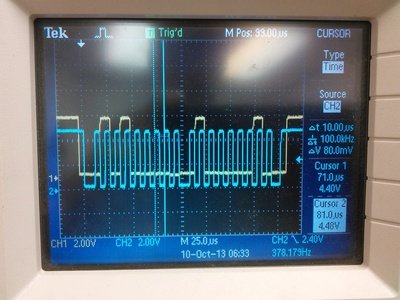
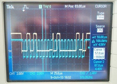
The above picture shows what the command to display an 'A' looks like from the Arduino.


i2c_t3.jpg
Above pictures shows what the same command looks like from the T3. Notice the rise in the SDA after the ACK, it happens after every ACK. I think it is the ACK, it rises just after the 9th bit.

I must also add that I can use the T3 to communicate to a different I2c board (ERE relay board) and it is successful and the same characteristic rise after the 9th (ACK) bit still exists.

Any help would be appreciated. Thanks for your time.

Addition: I enabled I2C_DEBUG and the display started to work. This isn't a solution but may help.

Addition 2013-10-12 : Evidently the Newhaven display can't handle the narrow pulse width after the ACK/NACK. I couldn't find a referenced that said exactly what the width had to be. I ended up putting a loop in the i2c0_isr that just counted to use some time.

for(xx=0; xx<10; xx++){ }, xx had to be declared as a volatile

The width widened and the display began to work. There has to be a better fix but for now this will work.
 
Last edited:
Sorry for the delay, I didn't get a forum notice (probably due to the recent spamming).

That is a curious thing. The "spike" is happening at the ACK handover. Basically at that point in the communication the Master releases the data line and the Slave pulls it low (that is the ACK). As long as the SDA spike occurs when SCL is low it is not in violation of the spec. That appears to be the case.

My guess here is that the resistor pullups are too low for the given communication rate (the pullups are too fast - the edge rate is too high, which is why the voltage jumps up quickly at the ACK handover). For a 100KHz rate (as given in your code), the resistors can be a higher value. Try using 10K or higher and see what happens.

The other alternative is to perhaps create a new slower rate (it would require digging into the I2C settings). To some extent the I2C module enforces latency timing according to the rate setup. Or as you have done, manipulate the ISR timing to slightly delay when things occur. But I really think the easier solution is to change the resistors.


EDIT: Sorry I looked at it wrong, the spike is after the ACK, not before it as I initially thought. It is when the Slave releases the bus and the Master takes over again. It really should not be causing a Slave problem. It is not a spec violation (since SCL is low), perhaps there is some wiring crosstalk to the SCL line on the Slave side? Regardless I would still try some slower resistors, 1Kohm for low rate like 100KHz seems too low for me.

Another minor thing - it looks like your are running 5V I2C bus. The datasheets are confusing, but I've read elsewhere that the I/Os really should be limited to 3.3V. See this thread. Since I2C uses a pullup resistor, it has inherent current limiting. Actually replacing your 1Kohm with 10Kohm will improve this situation as it limits the ESD diode current further.
 
Last edited:
Nox, thanks mucho for the very cool library.

Using the Teensy 3 as a master device, should the timeout feature in endTransmission and requestFrom allow code to not hang if the slave device SDA or SCL (or power) lines are physically disconnected, as in the case where the slave device is a sensor which has been removed entirely? Using the attached code, when I pull the SDA or SCL line out, the Teensy hangs unrecoverably.
 

Attachments

  • TestTimeout.ino
    6.2 KB · Views: 535
Last edited:
nox771 - Thanks for your reply. You are correct, spike is after the ack. When I lengthened the 'spike' communication began to work, well mostly. I have concluded that some of the issues are with the display. I tested the display with a couple different controllers and now they all give me the same, albeit inconsistent, results.

You are also correct, the display is 5V. I am using a NXP PCA9306 device to change the levels. 3.3 on the T3 side and 5V on the display side. I am confident that the level shifter isn't causing problems.

I will try different pullups and report back.

Thanks for your time.
 
Using the Teensy 3 as a master device, should the timeout feature in endTransmission and requestFrom allow code to not hang if the slave device SDA or SCL (or power) lines are physically disconnected, as in the case where the slave device is a sensor which has been removed entirely? Using the attached code, when I pull the SDA or SCL line out, the Teensy hangs unrecoverably.

A few things to try:

First, the timeout is intended only to prevent a particular command from hanging right at that point. The initial part of your readByte() routine is writing to the device. However the way I2C works, if the device is not present it will not ACK - so the Master (in your case the T3) will interpret it as a NAK. It will not timeout, since ACK/NAK is a normal part of the I2C communication it will occur very quickly. Timeouts are more for the case where you send a long data set to a Slave and it takes longer than it is supposed to (due to clock stretching, interference, whatever).

Looking at your code I don't think the Write section is needed at all. I can see that you are testing if the device is present, but it is not needed, the requestFrom() routine will get a NAK if the device is missing.

Also, the readByte() routine appears to be keeping the bus in a non-released state. I don't know if that can cause a problem during disconnect (if you get glitches on the wire I'm not sure what would happen). I would try changing I2C_NOSTOP to I2C_STOP on the requestFrom() command.

Finally, your routine looks like it will hang unless it gets read data (this is probably the problem). The following:
Code:
while(!Wire.available());
will hang if the Rx buffer is empty.

You need to decide what return value you want from the readByte() routine in cases where there is no device present, or for whatever reason it doesn't read anything. If you are ok with a zero return value in those cases then the routine can simplify to this:
Code:
byte readByte(byte address)
{
  Wire.requestFrom(VCNL4000_ADDRESS,1,I2C_STOP,1000); // this is a blocking command, so no need to poll Wire.available()
  return Wire.readByte(); // will return 0 if buffer empty
}

IIRC, the old Arduino lib used to return a signed int equal to -1 in this case. If you want a -1 value in cases where the buffer is empty, then use this:
Code:
int readByte(byte address)
{
  Wire.requestFrom(VCNL4000_ADDRESS,1,I2C_STOP,1000); // this is a blocking command, so no need to poll Wire.available()
  return Wire.read(); // will return -1 if buffer empty
}

Check if either of those can work for you.

EDIT: Sorry I see that your readByte() routine is feeding a memory address into the device, not just checking for connectivity. Try this instead:
Code:
// readByte(address) reads a single byte of data from address
byte readByte(byte address)
{
  Wire.beginTransmission(VCNL4000_ADDRESS);
  Wire.send(address);
  Wire.endTransmission(I2C_NOSTOP,1000);
  if(Wire.status() == I2C_WAITING) 
  { 
    Wire.requestFrom(VCNL4000_ADDRESS,1,I2C_STOP,1000); // this is a blocking command, so no need to poll Wire.available()
    return Wire.readByte(); // will return 0 if buffer empty
  }
  return 0; // some kind of error occured (NAK, Timeout), return 0
}
 
Last edited:
Wow! Thanks for doing this library! Will definitely try it on a project where the current Wire library is not quite what we want. In particular the Wire "wait forever if bus is low" behaviour, which according to the above post is *not* helped by timeout. This can happen if I2C has no pullups: then the slave makes no reply at all, as if the bus is not connected to anything.

Yes it is a bit vague which situations are handled by the timeout and which are not. I'll try and run some experiments and annotate which conditions should be detected. I believe some of the hanging bus conditions should work, but I forget off the top of my head, so I'll need to verify it first.

Some behaviors are not always fixable. Part of the problem with these things is that the chip vendors try to make the I2C hardware "smart", but in doing so it sometimes boxes in the behavior, at times in erroneous and uncorrectable ways. If a bus is missing it's pullups the Master device can't even output it's own clock, so something like that may hang the hardware.

When I get a chance I'll run some test cases and post results.
 
I did some testing on the timeout conditions. For a properly wired bus the timeouts should work as intended.

However if the pullups are missing this is what I've found:
- If SDA pullup is missing, but SCL pullup is connected, then the timeout should work ok.
- If SCL pullup is missing, then the code will hang at the endTransmission()/requestFrom() command. More specifically it is hanging at this point:
Code:
// we are not currently the bus master, so wait for bus ready
while(I2C0_S & I2C_S_BUSY);

The reason this occurs is that the device believes a 2nd master is controlling the SCL (this is by design, it is a part of the arbitration process). It is possible to modify the code to exit with an error at that point, but it would require checking and possibly looping on a return value from endTransmission()/requestFrom(). But that is just pushing the problem somewhere else - it is already effectively looping internally.

I think the better solution is really to make sure the bus is properly wired, even if there were some failure mode, the communication will ultimately not work anyway unless pullups are used.
 
Thanks so much for this library. I have used it in the past with a Teensy 3.0 board.

Forgive me if this is a stupid question, as I'm fairly new to the Arduino and Teensy environments. I recently purchased a Teensy 3.1 board and was trying to get a sketch that I had working on the Teensy 3.0 board on the new board. When I tried to do that, I get a whole bunch of errors:

TeensyAsJoystick.cpp.o: In function `SendByte(unsigned char, unsigned char)':
C:\arduino-1.0.5/TeensyAsJoystick.ino:141: undefined reference to `i2c_t3::beginTransmission(int)'
C:\arduino-1.0.5/TeensyAsJoystick.ino:142: undefined reference to `i2c_t3::write(unsigned char)'
C:\arduino-1.0.5/TeensyAsJoystick.ino:143: undefined reference to `i2c_t3::write(unsigned char)'
C:\arduino-1.0.5/TeensyAsJoystick.ino:144: undefined reference to `i2c_t3::endTransmission()'
TeensyAsJoystick.cpp.o: In function `SendByte':
C:\arduino-1.0.5/TeensyAsJoystick.ino:145: undefined reference to `Wire'
TeensyAsJoystick.cpp.o: In function `loop':
C:\arduino-1.0.5/TeensyAsJoystick.ino:29: undefined reference to `i2c_t3::requestFrom(int, int)'
C:\arduino-1.0.5/TeensyAsJoystick.ino:33: undefined reference to `i2c_t3::read()'
C:\arduino-1.0.5/TeensyAsJoystick.ino:31: undefined reference to `i2c_t3::available()'
C:\arduino-1.0.5/TeensyAsJoystick.ino:49: undefined reference to `i2c_t3::begin()'
TeensyAsJoystick.cpp.o: In function `usb_joystick_class::hat(int)':
C:\arduino-1.0.5\hardware\teensy\cores\teensy3/usb_joystick.h:112: undefined reference to `Wire'
TeensyAsJoystick.cpp.o: In function `setup':
C:\arduino-1.0.5/TeensyAsJoystick.ino:16: undefined reference to `i2c_t3::begin()'
C:\arduino-1.0.5/TeensyAsJoystick.ino:21: undefined reference to `Wire'
collect2.exe: error: ld returned 1 exit status


I have #include <i2c_t3.h> at the top of my sketch.

I'm probably doing something stupid, but I just wanted to check first - is this library compatible with the Teensy 3.1?

Thanks
 
That would be much easier to answer if you would include a short sketch that would allow us to reproduce the problem!
I work on a mac and to me the mixture of backslash and forward slash is really irritating.
 
I haven't played with the new library but the file i2c_t3.cpp in the v5 zip file needs to allow for the 3.1 board, modify it to read

#if defined(__MK20DX128__) || defined(__MK20DX256__)

(or there may be newer versions of the library that have already fixed this ...)
 
I'm probably doing something stupid, but I just wanted to check first - is this library compatible with the Teensy 3.1?

I recently got in a couple of the new 3.1 boards. I haven't tried them yet. As mentioned above the defines have changed, so it may be as simple as what manitou suggests. I've got a more complicated update planned, but I'll try and get a basic 3.1 update soon. For now, just try changing the define line manitou shows above (I expect that will probably work).
 
I haven't played with the new library but the file i2c_t3.cpp in the v5 zip file needs to allow for the 3.1 board, modify it to read

#if defined(__MK20DX128__) || defined(__MK20DX256__)

(or there may be newer versions of the library that have already fixed this ...)

Thanks manitou! That seemed to do the trick - the sketch now compiles without errors.
 
All, I've uploaded a new version of the library (v6) which has the following changes:

  • It now includes Teensy 3.1 support, including the 2nd I2C interface (I2C1) which works the same as Wire but is called Wire1.
  • The Wire1 interface can be configured to use pins 29/30 or pins 26/31. Unfortunately both sets of these are on the backside surface mount pads. Refer to the top post and code examples for information on setup.
  • Added a new header define to allow the library to be compiled as a single interface (I2C0-only) for cases where code/ram space is tight.
  • Also added some interrupt "flag" defines, which when set will toggle pins high when the I2C interrupts occur. This can be useful as a logic-analyzer trigger, or in determining interrupt timing.
  • Added two new examples, specifically for Teensy 3.1: quad_master and dual_bus_master_slave.
Regarding the new examples:

quad_master - this one creates a device capable of being a Master on 4 separate I2C buses. It uses both I2C interfaces and multiplexes on both sets of output pins for each interface. I think this might be useful for anyone using multiple Slaves having fixed identical addresses (maybe eliminate some I2C muxes).

dual_bus_master_slave - this creates a Master on one bus and a Slave on the other. These can then be connected together so it talks to itself. It seems silly at first - why would anyone want a device which talks to itself - but this actually creates a closed-loop test environment on a single-device. It is useful for developing Master/Slaves. One nice thing, is that when the code uploads it automatically resets both Master and Slave (I've had many cases of hung Slaves, which required pulling/reconnecting USB to restart them, so to me this is a bonus).


Although externally this will seem little changed, it was actually a pretty big overhaul on the code. I didn't want to have completely separate code for the two buses, so it was all rewritten to use dereferenced pointers instead of hardcoding. This allowed me to maximize function sharing, including the ISRs. In the end, this new structure allowed the multi-bus code to be only incrementally different size-wise from the old v5 code (on the order of ~100 bytes). Ram is a similar case when configured for single-bus. When configured as a dual-bus I get an increase of 320 bytes Flash and 628 bytes Ram (using default buffer sizes, which are fairly large but can be changed).

I've been running tests on it for a few days, and did manage to find and fix a couple bugs (mostly bugs only affecting the very high rates). As far as I know everything is working now. So I'll extrapolate and say that it's functioning perfectly :) (if anyone runs into problems let me know...)
 
Back
Top