New I2C library for Teensy3

I've got 5 teensy 3.1 linked together on SDA0-SCL0

Each teensy got 11 attiny 85 bootloaded with arduino linked on SDA1-SCL1

I would like to exchange data between the teensys at 2.4 mhz and then having each teensy talking to the tinys at 100 khz on the second i2c line. If i include both i2c t3 and wire.h it gives me a compile error.

How do i make this?
 
You really have not provided enough info to answer the question wether it will be possible to run all the Teesny 3.1s at 2.4 MHz.
Annyway, there is no reason to run the two libraries in parallel on the Teesny 3.1. The i2c_t3 library will communicate fine with the ATTinys at 100KHz.
You'll use the wire.h library only when programming the ATTinys.
 
As Headroom mentioned there is no reason to run i2c_t3 and Wire together. The i2c_t3 library is a superset of the Wire API, so it implements all the functions already. Moreover they use the same hardware peripheral, so running both of them at once is likely to cause problems.

You should be able to use both I2C interfaces from the T3.1 using i2c_t3, just refer to the examples (see top post in thread). However the library only works on Teensy3, so you will need to use a different library on the ATTiny devices.
 
You probably know this already, but in general for ATtiny85, there is no Wire.h either, but instead there is TinyWireM.h or TinyWireS.h, depending on whether your ATtiny85 is master or slave. In this case, I would imagine the ATtiny85's are slaves.

At times I've thought of writing a combined wire library for use in library functions, that would use virtual functions to do the actual i2c transfers. On a Teensy 3.x in the main .ino/.pde file you would include i2c_t3.h, in ATtiny85's you would include either TinyWire<x>.h, and in Uno's/Lenoardo's/Teensy 2.x's you would include Wire.h. That way you don't have to maintain 3 separate libraries of functions that do i2c stuff. Due to the way the Arduino IDE works, you would need to have 3 separate main programs, but you could move most of the code to a library if you routinely move projects from one processor to another.

The libraries that use i2c would need to take an argument for the Wire device to allow communication with more than one i2c controller.

<rant>
I realize that these libraries were often hacked together to meet an initial need, or were written for really small constraints, but at times I wish the infrastructure had been designed with an eye towards future growth. I also hate having to edit header files to specify things like screen sizes (for OLED monitors), when the user should be able to specify it as a parameter in the constructor.
</rant> :(
 
Last edited:
TinyWire.h seems like a pretty foolish design decision to me.

I'm sure it made good technical sense to a programmer, who wanted to make sure people knew it wasn't really the same software. We engineers are like that, generally risk adverse, so we tend to rationalize design decisions like this, that somehow it will be better for end users if it's clearly not the same code as Arduino's normal Wire.h. In truth, it's really just avoiding taking responsibility for a decision and committment to craft a drop-in replacement for such a well established API.

Of course, the net result is most of Adafruit's customers suffer needlessly when using Trinket with a huge Arduino code base with Wire.h in widespread use. If they merely changed the name, their product would "just work" in so many more cases.


Ok, there, I ranted too. Normally I don't rant like this, especially about other boards, and especially about awesome companies like Adafruit. But in this case, it's truly a silly decision that only hurts their own customers. I'm amazed it's gone on this long.
 
Last edited:
I don't recall if the Adafruit ATtiny85 supported TinyWire*.h (I don't have it in my trinket/gemma ide directories). They seem to have gone to using something called i2c.h instead of Wire.h/TinyWireM.h with some of the latest releases, which of course is yet another file.

Digispark and the MIT ATtiny85 distributions were the ones I saw TinyWireM.h. There were other Tiny*.h (TinyServo.h for instance) files that put me off doing more with the ATtiny85's.

I believe this is the source for the original TinyWireM.h: http://playground.arduino.cc/Code/USIi2c

And while we are ranting about incompatible changes others made, the decision of the Due 'designers' to put the SDA/SCL in the standard shield layout as the 2nd i2c device, means whenever I download a new i2c device, I need to check the code for crud like:

#ifdef __AVR__
#define WIRE Wire
#else
#define WIRE Wire1
#endif

because of course if it isn't an AVR it must be a DUE. This is why I feel the wire devices needs to be an argument to the data declaration.
 
Last edited:
You really have not provided enough info to answer the question wether it will be possible to run all the Teesny 3.1s at 2.4 MHz.
Annyway, there is no reason to run the two libraries in parallel on the Teesny 3.1. The i2c_t3 library will communicate fine with the ATTinys at 100KHz.
You'll use the wire.h library only when programming the ATTinys.
In Order to run the I2C bus at such high frequencies you need to keep the bus length very short. The issue is bus capacitance.
 
The i2c_t3 Example will not compile for teensy 3.1
Wire.begin(I2C_MASTER, 0x00, I2C_PINS_18_19, I2C_PULLUP_EXT, I2C_RATE_2400);
does not produce a valid F_BUS value?
 
The i2c_t3 Example will not compile for teensy 3.1
Wire.begin(I2C_MASTER, 0x00, I2C_PINS_18_19, I2C_PULLUP_EXT, I2C_RATE_2400);
does not produce a valid F_BUS value?

What bus frequency are you trying to use? At the moment the lib only supports 24MHz and 48MHz. It is on my to-do list to support more, but I haven't gotten there yet.

Edit: To be clear, for a 2400kHz I2C rate you would need to be compiling for either 96MHz or 48MHz frequencies. Are you set to one of those?
 
Last edited:
There does not seem to be an I2C_RATE_XXXX value for either 24MHz, or 48MHz. Am I missing something?

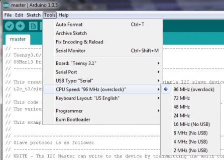
The bus freq is the internal freq of the ARM data buses. It is a setting which depends on the freq at which the T3 is run. For the Arduino IDE it is controlled by the menus:

screenshot.383.jpg

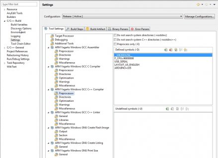
Both the 96MHz and 48MHz rates use an F_BUS setting of 48MHz. If you are building via some other IDE, eg. Eclipse, then it is set in the project properties (indirectly by setting F_CPU):

screenshot.384.jpg
 
Hi, I running a copy of the example code
// Teensy3 I2C Master Test
// 08Mar13 Brian (nox771 at gmail.com)
I'm using the Arduino GUI, and test shows Board "Teensy 3.1", and CPU Speed "72MHz"
In setup I have Wire.begin(I2C_MASTER, 0x00, I2C_PINS_18_19, I2C_PULLUP_EXT, I2C_RATE_400);
When I compile I get this error message
C:\Users\John Harris\Documents\Arduino\libraries\i2c_t3\i2c_t3.cpp:220:10: error: #error "F_BUS must be 48 MHz or 24 MHz"
So where in the code is F_BUS defined? I had this same problem in my own code, so I went to the Example code to find a fix.
 
I'm using the Arduino GUI, and test shows Board "Teensy 3.1", and CPU Speed "72MHz"
What speaks against setting the clock frequency in the ArduinoIDE to 96MHz or 48MHz as nox771 suggested in his last post ?

Also, if you are using the Arduino Eclipse IDE (or plugin) you can also set the Teensy Clock frequency in the Project properties and will end up with the correct F_BUS.
 
Sorry, but as I mentioned I don't have the 72MHz support in just yet (it is using F_BUS 36MHz). F_BUS is defined in the mk20dx128.h file, as follows:

#if (F_CPU == 168000000)
#define F_BUS 56000000
#define F_MEM 33600000
#elif (F_CPU == 144000000)
#define F_BUS 48000000
#define F_MEM 28800000
#elif (F_CPU == 120000000)
#define F_BUS 60000000
#define F_MEM 24000000
#elif (F_CPU == 96000000)
#define F_BUS 48000000
#define F_MEM 24000000
#elif (F_CPU == 72000000)
#define F_BUS 36000000
#define F_MEM 24000000
#elif (F_CPU == 48000000)
#define F_BUS 48000000
#define F_MEM 24000000
#elif (F_CPU == 24000000)
#define F_BUS 24000000
#define F_MEM 24000000
#elif (F_CPU == 16000000)
#define F_BUS 16000000
#define F_MEM 16000000
#elif (F_CPU == 8000000)
#define F_BUS 8000000
#define F_MEM 8000000
#elif (F_CPU == 4000000)
#define F_BUS 4000000
#define F_MEM 4000000
#elif (F_CPU == 2000000)
#define F_BUS 2000000
#define F_MEM 1000000
#endif

The blue choices above are what is supported at the moment. I'll see if I can rework to support all these. For right now you will need to choose one of the blue choices from the menu.
 
So I find changing the CPU clock speed to either 96MHz, or 48MHz, and the compile error goes away.
Great, now I can move on with my own code Thanks
 
I'm going to be getting data from i2c slave devices that can be hot plugged in and out (bad idea, I know), so I've been playing around with a way to make sendTransmission and sendRequest recover from bus lockups (I was running into them during testing).

In the library commented out the two instances of:
Code:
while(*(i2c->S) & I2C_S_BUSY);
Then, in my program, I accessed my i2c device with code similar to this (proof of concept):
Code:
     if(Wire.done()){
      if (millis() - last_sample > 50){
        Wire.sendRequest(target,256,I2C_STOP);
        last_sample = millis();
        count = 0;
      }
    }
    else
    {
      //set timeout here
      if (millis() - last_sample > 1000){
        //change i2c pins back to digital IO
        pinMode(19,OUTPUT);
        pinMode(18,INPUT);

        //watch for sda to go high
        //try pulsing the clock a max of 9 times
        while (digitalRead(18) == 0 && count < 10){
          //pulse clock once
          digitalWrite(19,HIGH);
          digitalWrite(19,LOW);
          digitalWrite(19,HIGH);
          count++;
        }
        //try to restart wire using initial settings
        Wire.begin(I2C_MASTER, 0x00, I2C_PINS_18_19, I2C_PULLUP_EXT, I2C_RATE_2400);
      }
    }

It seems to work, but I need to clean it up so everything isn't hard-coded, maybe factor out some bits and put it in a copy of the library. And I'm pretty sure this breaks all multi-master support.

I'm thinking that there really should be a delay between the digitalWrite commands proportional to the I2C rate, especially for slower devices, or maybe this delay could be handled by banging out the clock slowly over repeat calls so as not to block.... I'll have to think about it.

Any thoughts?
 
Last edited:
IIRC the library already has a timeout-&-restart feature to deal with bus lock- ups.
Some I2C hardware is designed to be hot pluggable e.g. Some I2C bus buffers allow hot plugging devices on the bus.
 
The timeouts in the library seem to only deal with slaves that go silent and disappear, I want to handle slaves that disappear and come back thinking they still need to send some data (and are trying to hold SDA low).

I Suppose I could also detect if something is holding SCL low, but there isn't anything that could be done about it (other than generate an error).

I probably shouldn't be commenting out "while(*(i2c->S) & I2C_S_BUSY)", I could add an adjustable timeout like everything else.
 
Last edited:
I realized that modifying the library would be a bit out of the scope of my quick little project, so I did what needed externally.

Here is an quick and dirty example that is non-blocking (As long as you stick to the non-blocking functions) and can recover from SDA being left down by a slave trying to send data.

View attachment master_example.ino

The only modification I did to the library (6b) was to comment out "while(*(i2c->S) & I2C_S_BUSY)".

You may need to add in a mechanism to slow down the bit-banging of the recovery clock depending on the devices you are using.
 
Initially I based my reset off of this: 3.1.16 Bus clear

Page 20: "If the data line (SDA) is stuck LOW, the master should send nine clock pulses. The device that held the bus LOW should release it sometime within those nine clocks. If not, then use the HW reset or cycle power to clear the bus."

That seemed to catch a lot of the problems, but occasionally it would still lock up afterwards with both SDA and SCL high.

Then I found this: Solution 1: Clocking Through the Problem

Page 2: "It is the master’s job to recover the bus and restore control to the main program. When the master detects the SDA line stuck in the low state, it merely needs to send some additional clocks and generate a STOP condition. How many clocks will be needed? The number will vary with the number of bits that remain to be sent by the slave. The maximum would be 9."

OK, so I need to bit bang a STOP condition... K20 Sub-Family Reference Manual

Page 1185: "The master can terminate the communication by generating a STOP signal to free the bus. A STOP signal is defined as a low-to-high transition of SDA while SCL is asserted. The master can generate a STOP signal even if the slave has generated an acknowledgement, at which point the slave must release the bus."

My final code looks like this:
Code:
void unlockthebus(void){

  Serial.println("Resetting i2c Bus...");

  //change i2c pins back to digital IO
  pinMode(19,OUTPUT);
  pinMode(18,INPUT);

  int count = 0;
  
  //watch for sda to go high
  //try pulsing the clock a max of 9 times
  while (digitalRead(18) == 0 && count < 10 ){
    //pulse clock once
    digitalWrite(19,HIGH);
    digitalWrite(19,LOW);
    digitalWrite(19,HIGH);
    count++;
    Serial.println(count);
  }

  //bit bang a stop
  pinMode(18,OUTPUT);
  digitalWrite(18,LOW);
  digitalWrite(19,HIGH);
  digitalWrite(19,LOW);
  digitalWrite(18,LOW);
  digitalWrite(19,HIGH);
  
  //try to restart wire using initial settings

  Wire.begin(I2C_MASTER, 0x00, I2C_PINS_18_19, I2C_PULLUP_EXT, I2C_RATE_2400);

  Serial.println("Fixed.");
}

I didn't need any delays between writing bits, but this will likely depend on your device. It would be best to bit bang at a speed similar to your i2c bus.

Then I altered sendTransmission and sendRequest to return true or false depending on I2C_S_BUSY. This way I can't get stuck in the while loop with a hung bus.

I replaced:

while(*(i2c->S) & I2C_S_BUSY)

with:

if(*(i2c->S) & I2C_S_BUSY){
return false;
}

(This could have an timeout before returning false if desired.)

I'll upload some full example code once I get it cleaned up...
 
This is an interesting idea. The overall idea seems reasonable, although pulsing single clocks instead of blocks of nine might be better. I don't know if it makes sense to roll this into the main library calls or if it is better served as an example. I could add this technique as a bundled example.

The trouble with incorporating this as a part of the library is that it is specific to a particular setup (single master, immediate call). By making the library call immediately exit if busy, it requires the user code to expect this situation. I'm wondering in particular about background calls where it is used in more of a launch and forget manner. I'll need to think about this some more.

Regarding the STOP I don't know if a bit-bang solution can work. That would require muxing the I2C peripheral off the pins, do the bit-bang, and then muxing it back in (however it's internal state might still think it is in a busy state). I'll try and study this and see if there is a clean way to exit this stuck condition.
 
While I seem to have it working, my solution doesn't seem to agree with the datasheets... I ended up doing a lot of trial and error until I could get the bus to reliably recover. After I got it working well enough, I set up a little machine with relays to continually connect and disconnect SDA and SCL quickly for a few hours as a stress test. Not very scientific, but it survived, which is good enough for me.

I also had to add a status reset to the start of begin() to prevent some other lockups.

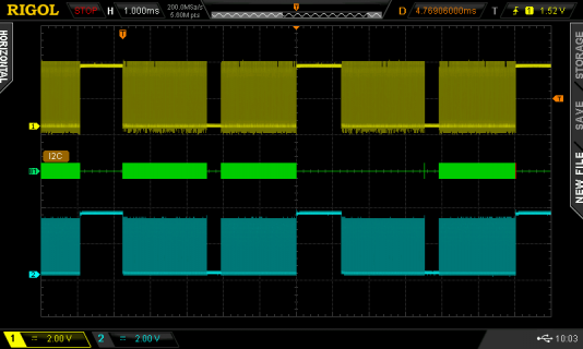
Attached is the scope outputs between two Teensy 3.1s. I was able to get about 700kbit/s half duplex (with no CRC8 errors), with a bit of bus time unused. The master uses about ~8% of the CPU time on a 96mhz Teensy 3.1, but it's difficult to measure with only micros().
Scope1.png

Slightly modified library
View attachment i2c_t3.cpp
View attachment i2c_t3.h

Master and Slave example
View attachment master.ino
View attachment slave.ino
 
Last edited:
I need to do non-blocking write then read requests to an ic2 client (I am the master) in order to read the value of a register on the client.
I have looked at the various methods and the code, and I see that the low level code is capable of doing a transmit followed by a receive, but I can only see how to do a general request (i.e. address the client's address with the read bit set) not how to set up a write of the address (with read bit) and the register number followed by a receive. Is this possible, if so how, if not what is the simplest way to do a register read in a non-blocking fashion?
 
You could do something like my Non-Blocking master example from one post above. You'd likely adjust the mode 0 section to write whatever the command byte is instead of a whole array like I was doing.

You don't need to use my modified library unless you have problems with the i2c bus locking up.

First I'd set the address you want to read:

Wire.beginTransmission(slave_address);
Wire.write(slave_registery_address);
Wire.sendTransmission(I2C_NOSTOP); //Nostop because we are reading the data we requested next

Wait for sendTransmission to finish then...

Wire.sendRequest(target,MEM_LEN,I2C_STOP) //request and start reading in the data, with a i2c_stop at the end

Wait for sendRequest to finish then....

while(Wire.available()) {
recbuffer[index++]= Wire.readByte(); //read the data sitting in the i2c buffer into an array (check bounds if this is real code)
}


I split the various i2c writes and reads into modes that increment after completion, that way I can keep looping through my main loop without blocking.
 
Last edited:
Back
Top