teensy 3.0 SPI with DMA -- nice try

Status
Not open for further replies.
All internal peripherals are an example for that because there is no theortical imit on libraries that might use a resource, and we can never be sure that a user doesn't use two libraries that access the same resource.

We have two options:
  • Let users decide if libraries go well together
  • Create some way of finding out at compile time if two libraries in a specific configuration go well together (static assertions? Lots of template magic)

Suggestion for easy way to help people avoid odd crashes/deadlocks due to lack of knowledge of resources used within multiple libraries. No code; less politics:
Maintain a document within the library top folder for Teensy that lists each library stating which on-board (K20) peripherals are used directly (not via other library calls), E.g.,

MyGreatLib
----------
SPI0: Yes
DMA: Yes, #0, #1
I2C: NO
NVIC interrupts: Yes, SPI0, DMA complete
Pin remapping: None

Then people in the know can avoid surprises, and avoid poring over other people's library code to see if there would be a conflict.
People who aren't that tech savvy could at lease see that there may be a conflict and ask questions.
 
Last edited:
Probably not that bad. Now we just need to point people at that readme:
Code:
#ifndef MYGREATLIB_IKNOWTHERISKS
#warning Be sure to read the MyGreatLib README to avoid hardware conflicts
#endif
(no joke)

And they can get rid of the warning by #define MYGREATLIB_IKNOWTHERISKS
 
What else (apart from zipping) do I have to do to turn this into a library? I usually only use the teensyduino files in my own build environment.
its pretty easy...
put all the .h & .cpp files into a folder called whatever you decide the library should be named, then create a sub folder called "examples" and put any examples into that. then zip the library folder.

Note that above code is not meant to be "used", consider it alpha. Coming up with useful example is tough, as they would all be tightly coupled to properly set up hardware.
Just append "_alpha" to the library name, that should be clear enough, as far as examples maybe just something to show how to use the function like you did but for arduino. Many more people would try this i think if it where a library for Arduino IDE also.


here, i've done it for you, hope you don'y mind, but it should show you how if you ever update it. Then you can add in version numbering also.
 
Last edited:
Not quite: When you download the repo as a zip, it's called DmaSpi-master.zip which could confuse the arduino IDE. I'll add installation instructions to the readme.
 
Here are some SPI+DMA performance numbers writing 1000 bytes on unconnected SPI with teensy 3.0 and 3.1.
Code:
              t3    t3.1    SPI0_CTAR0  SPI clk
              17.94 18.02 mbs b8000000  24mhz
              13.51 13.56 mbs b8010000  16 mhz
              10.55 10.58 mbs 38000000  12mhz   default rate in library
               7.48  7.48 mbs 38010000   8mhz
               3.98  3.99 mbs 38000002   4 mhz
               2.06  2.06 mbs 38010003   2 mhz  
               1.05  1.05 mbs 38010004   1mhz
For comparison, here are unconnected SPI performance for Teensy and other MCU's (DUE maple ...)
https://github.com/manitou48/DUEZoo/blob/master/SPIperf.txt
The spi4teensy3 (and teensy SPI in SD FAT lib) are a bit faster at the higher SPI clock rates, but of course the DMA allows the MCU to do other things whilst the DMA is running.
 
Thanks for those numbers! Do the other tests store received data as well? I'm trying to figure out why the DMA SPI is slower, because the DMA controller should be able to fetch data just as fast as it comes in through PUSHR and POPR.
 
Last edited:
Thanks for those numbers! Do the other tests store received data as well? I'm trying to figure out why the DMA SPI is slower, because the DMA controller should be able to fetch data just as fast as it comes in through PUSHR and POPR.
The tests were write-only (received data was ignored).
:rolleyes: Note, I haven't actually hooked the SPI+DMA to a device to see if it's actually "working", though I do plan on hooking SPI pins to logic analyzer ...
and thanks for figuring out how to implement the SPI+DMA!
 
With logic analyzer hooked up to SPI+DMA test, i see reasonable SPI CLOCK rate and MOSI is counting up as per sketch, and MISO is 0, but CS (pin 13) stays 0? Is that what's expected? Usually CS is low only during the data transfer. The analyzer triggers on SPI CLK rising, so maybe CS just stays LOW or did I miss something with ChipSelect?
UPDATE: problem was the example uses LED_BUILTIN for the CS -- Eeeek, bad choice, that is pin 13 which is SPI's CLK pin! I changed to use pin 10, and logic analyzer data looks OK

here is my corrected timing sketch

Code:
// test a SPI DMA lib
// http://forum.pjrc.com/threads/23253-teensy-3-0-SPI-with-DMA-nice-try
// https://github.com/crteensy/DmaSpi
//  hack SPI speed in DmaSpi.h


#include "DmaSpi.h"
#include "ChipSelect.h"
// create a chip select object. 
ActiveLowChipSelect<10> cs;

#define SPI_BUFF_SIZE 1000
uint8_t source[SPI_BUFF_SIZE];

void setup()
{
  int i;
  Serial.begin(9600);
  DMASPI0.begin();
  for (i=0;i<SPI_BUFF_SIZE;i++) source[i]=i;
}

void loop() {
    uint32_t t1;
    double mbs;
    char str[64];

    t1 = micros();
	DmaSpi0::Transfer trx(source, SPI_BUFF_SIZE, nullptr, 0xFF, &cs);
	DMASPI0.registerTransfer(trx);
	while(trx.busy());
    t1 = micros() - t1;
    mbs = 8*SPI_BUFF_SIZE/(float)t1;
    sprintf(str,"%d us  %.2f mbs %0x",t1,mbs,SPI0_CTAR0);
    Serial.println(str);
    delay(3000);
}
 
Last edited:
The CS pin is not going low because there was a bug lurking in ActiveLowChipSelect's internal Init class.

Workaround: Just initialize the pin wherever you like for now, I'll fix the code on github later today.
 
The CS pin is not going low because there was a bug lurking in ActiveLowChipSelect's internal Init class.

Workaround: Just initialize the pin wherever you like for now, I'll fix the code on github later today.

I edited my message. Your example was using pin 13 for CS, that is SPI's CLK pin ??? I changed it to 10, and that made logic analyzer traces look good.
 
Indeed, using the LED pin was a silly choice in my example, I'll change that.

That it works now confuses me a bit, because I had to change the initialization code in my local copy to get it to work correctly. I'll investigate a bit further.

Maybe this is obvious, but you can test reading from SPI by shorting MOSI and MISO. Then create a "copy" of an array over SPI:
Code:
const uint8_t size = 10;
uint8_t source[size] = {0, 1, 2, 3, 4, 5, 6, 7, 8, 9};
uint8_t dest[size] = {0};
DmaSpi0::Transfer trx(source,size,dest); // you can omit the fill value and cs
DMASPI0.registerTransfer(trx);
while(trx.busy());
Serial.printf("memcmp result = %d\n",memcmp(source, dest, size)); // result should be zero if dest is a copy of source now
This is untested, but I successfully ran code like that yesterday. It's just written down from memory now.

Regards

Christoph
 
I
That it works now confuses me a bit, because I had to change the initialization code in my local copy to get it to work correctly. I'll investigate a bit further.

just for the record, i have been using the code from your attachments and haven't checked if it's different from your github.
 
Wow, I didn't even include ChipSelect.h in my github repo...I need a vacation. I added ChipSelect.h and changed the example to use pin 14. That clearly demonstrates that CS is not limited to the mk20dx's native CS pins
 
I'm trying to figure out why the DMA SPI is slower, because the DMA controller should be able to fetch data just as fast as it comes in through PUSHR and POPR.

I'm guessing the DMA SPI might be slower than the SDFAT lib SPI, because the SDFAT lib uses 16-bit FIFO. If I run the SDFAT spiperf with 8-bit FIFO enabled, then the datarate drops from 21.86 mbs to 18.88 mbs.

the other timing curiosity for slow speed SPI (e.g. 1 mhz), is that data rate (1.05 mbs) is faster than clock rate!. this is because delay between bytes is less than 0.5 us (clock pulse width). later versions of SDFAT lib added CSSCK bits to SPI0_CTAR0 which expanded the delay between bytes, presumably some devices weren't happy with the tiny delay between bytes ...
 
Last edited:
For sanity test, I hooked up a DS3234 (RTC) and that worked with SPI+DMA -- ran at 4 mhz and it needed CPHA 1 in SPI0_CTAR0 (mode 1). SPI0_CTAR0 = 0x3a000002;

I also confirmed that cycles were "available" during DMA with
while(trx.busy()) idle++;

SPI+DMA looks good.
 
Last edited:
Experimental:

Create a custom chip select class that sets SPI0_CTAR0 to whatever you need for that specific chip - that way you can mix chips with different requirements on the bus, and you don't need to take care of cleaning up afterwards:
Code:
template<unsigned int pin>
class Ds3234ChipSelect : public AbstractChipSelect
{
  public:
    Ds3234ChipSelect()
    {
      static Init init; // configure the pin
    }
    void select() override
    {
      SPI0_CTAR0 = SPI_CTAR_FMSZ(7) | SPI_CTAR_CPHA | SPI_CTAR_BR(2);
      digitalWriteFast(pin, 0);
    }
    void deselect() override
    {
      digitalWriteFast(pin, 1);
    }
  private:
    /** Configures a pin as output, high **/
    class Init
    {
      public:
        Init()
        {
          pinMode(pin, OUTPUT);
          digitalWriteFast(pin, 1);
        }
    };

// static Init m_init;
};
Btw, I think it's way cleaner and more readable to use the macros defined in mk20dx128.h for setting up the CTAR (SPI_CTAR_FMSZ(n) for example, which sets the frame size to 8 for n=7). They are well commented and consistent with the datasheet.

Regards

Christoph
 
Last edited:
Christoph,

thank you very much for your contribution. I hope next week I'll be able to test it with my data logger. For a first try, I'll go with the RawWrite example from SdFat (using SdFile::createContiguous, SdCard::writeStart and SdCard::writeData), to avoid jitter due to FAT operations and in order to simplify the non-blocking code. I'll let you know about the results.
 
I'd love to see it working! Please tell me if you encounter any limitations of the DmaSpi interface that might become a show-stopper.
 
This is basically exactly not what you (jbliesener) are trying to achieve, BUT:

With a bit of management, DMA SPI and SdFat happily coexist. I can now feed my display and have a file open for reading. It's not totally straight forward, though:
Code:
// this is a non-blocking request:
DMASPI0.pause();
// only when the DMA SPI driver finished a running transfer it can release the SPI:
while(!DMASPI0.paused());
DMASPI0.releaseSpi();

... do SdFat stuff

DMASPI0.resume();
I'll do some more testing and then commit the changes on github.

Regards

Christoph
 
Scatter/Gather emulation and a small problem

Dear Christoph,

again, thank you very much for your library. I am starting to implement it into other libraries and, yes, it is a huge step forward.The broken scatter/gather feature on the chip sucks, but with a very simple fix on your architecture, we can compensate for that. I added another boolean field called "m_bDontDeselect" to the DmaSpi0::Transfer class. The ISR queries this field upon a completed transfer and, if it is set, it doesn't deactivate the CS line. The next transfer can then continue the work of the previous one, effectively concatenating any number of registered transfer objects into a single SPI transaction. So, given an additional constructor for the Transfer object

Code:
  Transfer(const uint8_t* pSource = nullptr,
  const uint16_t& size = 0,
  volatile uint8_t* pDest = nullptr,
  const uint8_t& fill = 0,
  AbstractChipSelect* cb = nullptr, 
  boolean dontDeselect = false)

I can now send a single command byte followed by a whole buffer passed from an upper layer, without needing to copy around the buffer:

Code:
void Enc28J60Network::writeBuffer(uint16_t len, uint8_t* data) {
  uint8_t cmd = ENC28J60_WRITE_BUF_MEM;
  DmaSpi0::Transfer trx0(&cmd,1,nullptr,0,chipSelect,true);
  DmaSpi0::Transfer trx(data,len,nullptr,0,chipSelect);
  DMASPI0.registerTransfer(trx0);  DMASPI0.registerTransfer(trx);
}

While this works great, another feature gives me some headache. I took a look at your pause() and resume() methods, that, for some reason, I need to switch between polled and DMA mode. The problem is that when I switch to polled mode and back, the DMA ISR is triggered ONE BYTE BEFORE the end of the transfer. Take a look at the following code:

Code:
while (1) {
  uint8_t data[]={0xf0, 0xa5, 0x03};
  DmaSpi0::Transfer trx(data,3,nullptr,0,&cs);
  DMASPI0.registerTransfer(trx); // transfer 3 bytes through DmaSpi
  while (trx.busy()); // wait until complete

  DMASPI0.pause(); // switch to polled mode
  SPDR=0x0;  // transfer a single byte with Paul's avr emulation, don't care about CS 
  while(!(SPSR&(1<<SPIF)));    // wait for transfer to complete
  DMASPI0.resume();  // back to DMA mode


  DMASPI0.registerTransfer(trx);  // 3 bytes through DmaSpi
  while (trx.busy()); // wait until complete
}

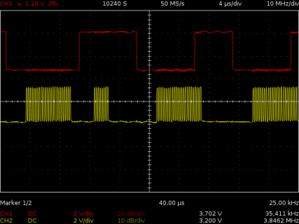
Please take a look at the attached scope picture, that shows CS and CLK. The first transfer (3 bytes through DmaSpi) correctly lowers and raises CS before and after the transfer. The second transfer sends out a single byte, but doesn't care about CS. However, after that, all following DmaSpi transfers raise the CS pin during the still ongoing transfer.

Actually, the DMA ISR gets called after the SECOND LAST BYTE. This seems to be independent from the number of bytes sent before through DmaSpi or through polling. Any number of bytes written directly to the (emulated or not) SPI registers lead to a premature ISR trigger ONE BYTE before the end of the transfer.

Do you have an explanation or solution for this?

Regards

Jorg
 

Attachments

  • scope.png
    scope.png
    40.6 KB · Views: 124
Last edited:
I'll take a closer look tomorrow, but my first guess is that resume() doesn't clean up correctly. There are a lot of bits that might affect a following DMA transfer...
 
Status
Not open for further replies.
Back
Top