Teensy 3.0 with LED array

Status
Not open for further replies.
Hi!

I'm new to the forum as well as electronics in general.

I've been in touch with Paul Stoffgren about this, but thought I would bring my discussion to the forum for public searchability.

I'd like to power an array of fading LEDs with the Teensy. The array will not be on a matrix, but rather on a string that I've soldered together. So far, I have them soldered in parallel. I may upgrade to an LED strip within the next few days, specifically the LPD8806. For the time being, however, I'll be sticking with my self-made string of LEDs.

Since my knowledge is very rudimentary, I don't know the best way to connect the LEDs to the Teensy or which code to use. I've been searching for "fading array arduino" on Google but the results are surprisingly unhelpful. We all have to start somewhere :D

Thanks!

Steve
 
Do you have a schematic or even a photo of how you've built these LED strings? Knowing how they're physically connected would really help to give you accurate advice.
 
sure thing! here you go:

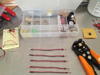
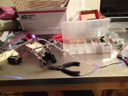
photo2.jpgphoto1.jpg

(apologies for the delay, the web uploader for this page doesn't seem to play well with safari so I moved my images to a hosting site)
 
You do want to fade them all on and off at once?

You'd probably use a (power) MOSFET to drive the LEDs, via a PWM output on the Teensy.

Basically drive the MOSFET from a PWM out of Teensy, via a resistor to limit current (1k or so perhaps?). Source of the MOSFET to GND. You'll also want a largish resistor between Gate and Source, 100k or thereabouts. The cathodes (-ve) of the LEDs (via resistors) are then connected to the Drain on the MOSFET.

You can then use the analogWrite() function to specify the "brightness" of the pin (via PWM), and fade it or whatever you want.

Keep in mind, if you're running a long wire of these you might see some dropoff in brightness as it goes along. You could do it in a loop to help minimise this.

Also, if you're running it anywhere hostile, that might pick up spikes or other nastyness, you could consider running the PWM through an optocoupler prior to the MOSFET, to protect the teensy.

Anyway, you should be able to find some schematics/info by googling MOSFET PWM LED driver or something along those lines.

- Peter
 
Last edited:
Thanks Peter!

I'm not familiar with MOSFET, so I'm going to do some googling.

Re: dropoff in brightness . . . there most certainly is. How would you suggest I do it in a loop? Sorry if that's an obvious question . . . like I said, I'm new.

Thanks again!

Steve
 
It's difficult to see how those resistor are connected. They look like they might be 220 ohms? Each looks like it's in series with a LED, but I can't quite tell for sure.

First of all, you should test your LED strip by simply connecting it to +5 volts. I didn't want to write this earlier, since I had no idea if you were using resistors. I'm still a little uneasy giving you this advise without a good photo or schematic, but there are resistors. Just know that if you ever connect a LED directly to power without a resistor, it will likely be damaged.

So, when you connect them all directly to 5 volt power (no Teensy involved), all the LEDs should light at equal brightness. You can use a voltmeter at both ends of the cable, to verify you have a consistent 5 volt power down the entire line. Going from 5.0 at the input to 4.9 or even 4.8 at the output is probably fine, but if you're ending up with only 3.5 at the end, then you know you've got a problem.

Peter is right, you'll need a transistor, since a Teensy pin can not deliver that much power. Here's another message I wrote, showing how to use a TIP102 transistor to turn power on/off to a pump. Your LEDs are pretty much the same thing, except the diode isn't as critical since you don't have a magnetic field like motor would.

http://forum.pjrc.com/threads/1840-Controlling-a-pump-with-teensy3?p=3297&viewfull=1#post3297

Hopefully this helps?
 
Paul,

Thanks again for your help on this.

Yes, the resistors are 220 ohms, in series. I've been connecting them to a 9v battery, and they are roughly equal. There is some dropoff in luminescence among the five LEDs in the string (versus if the LED is isolated/not in a string), but that was something I expected.

I do have some transistors. What type would you suggest (is this the TIP102 you mentioned?)? And where would I physically attach it to? Teensy? The LED? Apologies if this is in the link you included (http://forum.pjrc.com/threads/1840-Controlling-a-pump-with-teensy3?p=3297&viewfull=1#post3297), I'm still trying to decipher it.

As far as the Teensy, I didn't order pins with it, so the outputs are exposed. I suppose the LED strings will require soldering directly to the Teensy board?
 
Just an update on my end. I picked up the TIP120 as well as a Mosfet IRF510 (the only one they had at Radio Shack). I'm currently in the process of researching means of physically incorporating into my circuit, since I've never used one before.

I have a few Adafruit Perma-Proto boards, two of which I've set up 555 Timers on for a separate circuit. I hope to set up a third with the Teensy, if that's even necessary . . . I'm still not sure as the best way to build the Teensy circuit.

Finally, I came across this code which I think will accomplish the effect I'm after:

http://arduino.cc/forum/index.php?P...35135d245a2d&topic=118230.msg899929#msg899929

Any guidance on this as well as previous unresolved issues still welcome!
 
The IRF510 probably will not work. Those types of MOSFETs normally need a 10 or 12 volt driver.

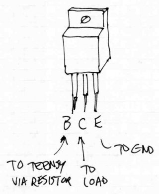
Here's a quick diagram that might help...

TIP102.jpg
 
Paul,

Thanks for the drawing! It's helpful, but I'm still having a hard time visualizing what the finished circuit will look like once the teensy is integrated with all the components.

As I've gradually acquired more knowledge, I'm wondering if it will be possible to do this on a relatively compact scale, or to save my Teensy for another project down the road (once it goes into this, it's bye-bye forever, until I buy another).

Your wisdom (and awesome product) is appreciated!
 
I've kept working at this and did my first attempt at plugging in the Teensy (up until now, I had been in the research phase). Apologies if this is all very rudimentary . . . as I mentioned, I'm still very new to all of this.

As expected, it was blinking when plugged in. I followed the instructions to load the "blink fast" hex file (which I downloaded as a zip file from github, since it was downloading as a txt file through the Teensy site), but nothing changed on the Teensy. As suggested by the graphic in the Teensy software window, I pressed the button, which deactivated the blinking. Could this be the HalfKay file? The Teensy software indicated, as expected, that blink_fast.hex was running, 0% used.

I then tried using the Arduino software and tried to activate the blink example under the Teensy menu there. Still no change.
 
If you're using Teensy 3.0, you must use Arduino. Do not use the 2.0-only stuff (there's a notice at the top of the page about where to go for Teensy 3.0).
 
Status
Not open for further replies.
Back
Top