Well I was writing up my troubleshooting question and in writing it finally figured out what could be happening. Instead of not posting my question, I thought I'd write it up as a good example of unexpected problems one can have with AGND and GND.
My original request for help
-----------------------------------
I am using an interrupt timer to drive my ADC sampling. I'm using 2 buffers, so that one can be written to sdcard while the other one is still collecting samples.
I'm at a loss for the behavior I'm seeing. At first I thought it must be my code, but from testing it seems more likely to be something electrical.
There is a considerable voltage offset depending on which buffer was written to the sdcard.
At first I tried moving to different pins. Still there.
If I write known data to the buffers (instead of sampling the pins) in the interrupt, I don't get an offset.
The offset appears to be different whether I have the pin floating, or connected to AGND, but there is always an offset. If I jumper the 2 pins that I'm sampling, the offset goes away. I assume that implies that there is an actual voltage offset.
I don't think it's the writing to sdcard, because I would expect it to be more transient, and not the exact length of the buffer.
What could be the problem?
-----------------------------------------------
Ok, in realizing that my reference could be a problem I checked the ground on the sdcard and it was using AGND.
Switching from AGND to GND and it seemed to fix the offset.
I was thinking that using digital ground would produce more spurious activity, but not an offset that would last the whole length of my buffer (10 seconds).
Is it the switching of pins and the sdcard creating the offset? It's difficult to imagine that accessing a different segment of RAM would create the offset.
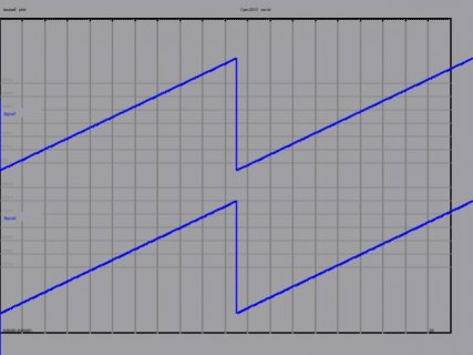
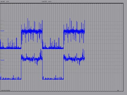
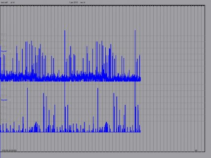
Top signal is 50Hz or 100Hz, bottom is 50Hz or 25Hz (1/2 of top). Values on y-axis represent signed int value of ADC.
Left is known values inserted. (20 seconds with 2 buffers of 10 seconds)
Middle is everything connected to AGND (40 seconds with 4 buffers of 10 seconds)
Right is AGND for sampling pins, GND for sdcard (40 seconds with 4 buffers of 10 seconds)


Everything is still noisier than I would have expected, but one problem at a time.
My original request for help
-----------------------------------
I am using an interrupt timer to drive my ADC sampling. I'm using 2 buffers, so that one can be written to sdcard while the other one is still collecting samples.
I'm at a loss for the behavior I'm seeing. At first I thought it must be my code, but from testing it seems more likely to be something electrical.
There is a considerable voltage offset depending on which buffer was written to the sdcard.
At first I tried moving to different pins. Still there.
If I write known data to the buffers (instead of sampling the pins) in the interrupt, I don't get an offset.
The offset appears to be different whether I have the pin floating, or connected to AGND, but there is always an offset. If I jumper the 2 pins that I'm sampling, the offset goes away. I assume that implies that there is an actual voltage offset.
I don't think it's the writing to sdcard, because I would expect it to be more transient, and not the exact length of the buffer.
What could be the problem?
-----------------------------------------------
Ok, in realizing that my reference could be a problem I checked the ground on the sdcard and it was using AGND.
Switching from AGND to GND and it seemed to fix the offset.
I was thinking that using digital ground would produce more spurious activity, but not an offset that would last the whole length of my buffer (10 seconds).
Is it the switching of pins and the sdcard creating the offset? It's difficult to imagine that accessing a different segment of RAM would create the offset.
Top signal is 50Hz or 100Hz, bottom is 50Hz or 25Hz (1/2 of top). Values on y-axis represent signed int value of ADC.
Left is known values inserted. (20 seconds with 2 buffers of 10 seconds)
Middle is everything connected to AGND (40 seconds with 4 buffers of 10 seconds)
Right is AGND for sampling pins, GND for sdcard (40 seconds with 4 buffers of 10 seconds)


Everything is still noisier than I would have expected, but one problem at a time.

