Industrial Pressure Transmitter Wiring

Status
Not open for further replies.

Blazanor

New member
I am trying to connect with the output from an industrial pressure transmitter which outputs a signal in the 4-20mA range. I know that I will need a 250 ohm resistor connected in order to retrieve a reading on the analog pins, but I am not entirely sure how to wire the whole circuit. I am using the Teensy 3.0 on a solderless breadboard.

The spec sheet for the pressure sensor that I am using can be downloaded from (http://www.wika.co.za/F_20__F_21_en_co.WIKA). I have also attached it. Please note that the first page is the cover and the subsequent pages are landscape with two pages side by side, so you may need to scroll horizontally to view odd numbered pages.

Any guidance would be much appreciated.

View attachment OI_2103870_F_2X_GB_D_6264.pdf
 
I would use a 60 ohm resistor, not 250. That will give you 0.24 to 1.2 volts, which nicely matches Teensy 3.0's analog input with the internal reference is used.
 
Thank you for your suggestion I will give it a go.

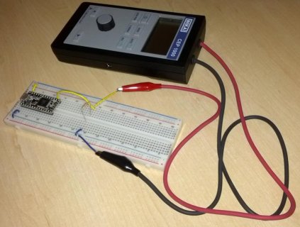
Here is a picture of what I have put together so far. I am using a Milliamp Calibrator to generate the 4-20mA signal for testing. At the moment I am using a 220 ohm resistor as it is all that I have on hand but I will swap it out for the 60 ohm as you suggest.

IMG_20130418_200649.jpg

The transmitter offers a 2 or a 3 wire connection:
2-wire Two connection lines are intended for the voltage supply. The supply current is the measurement signal.
3-wire Two connection lines are intended for the voltage supply. One connection line is intended for the measurement signal.

U+ Positive supply connection
U- Negative supply connection
S+ Positive measurement connection

Inside the transmitter are 5 connection terminals and the wiring is detailed as follows:

* Connect the instrument to earth via the pressure connection and/or connection terminal 5.
* Operate the pressure transmitter with a shielded cable and earth the shield at least on one side of the cable, if the cable is longer than 30m (2-wire) or 3m (3- or 4-wire), or if it is run outside of the building.

2-wire: U+ = 1 ; U- = 2 ; Test+ = 3 ; Test- = 4 ; screen = 5
3-wire: U+ = 1 ; U- = 2 ; S+ = 3 ; screen = 5

Since the cable to the transmitter is going to be more than 30 meters I will be using the 2-wire connection. My assumption is that in my circuit below I would connect the positive (yellow wire) to terminal 1 and the negative (blue wire) to terminal 2 on the transmitter. The transmitter will have an external power supply and my concern here is that it runs off DC 11-30 V so I would assume I would need to connect some more resisters here to drop it down to the 5V range.

Am I on the right track here or am I missing it completely? I really am a beginner here so I apologize for my ignorance.
 
Last edited:
Status
Not open for further replies.
Back
Top