Hi,
Thanks to Paul for making the Teensy 3 available. I am just starting a project with it. The final aim is to make an analogue synthesiser controller/sequencer based on (and expanding) the functions of the 1970s EMS AKS keyboard. http://en.wikipedia.org/wiki/EMS_Synthi_AKS This used a single sided PCB as a capacitive keyboard sensor, with some clever discrete logic and shift registers to make a basic 256 step sequencer.
I've started by experimenting with multiplexing a touchRead pin on the Teensy.
The full keyboard will have 30 key sensors and a number of control touch 'buttons', so I'm planning on using 3 74HC4067 chips to give me a maximum of 48 touch inputs. Control voltage output will probably be handled by a MCP4822 DAC. My plan is to have a separate keyboard PCB, and a smaller control board with the Teensy and other chips on it. The two would be connected using PCB headers.
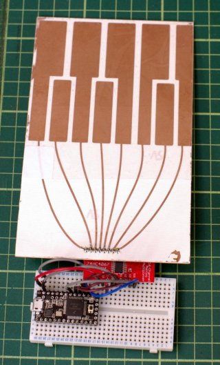
My test for the keyboard uses a 74HC4057 on a breakout board, breadboarded to the teensy and a home etched touch panel with 8 'keys' on it. Some clear sticky tape covers the touch surface. For this test I only have 8 inputs of the 16 connected.

I'm finding using the multiplexer readings from the touchRead pin seem to have a very high base level (around 3000 with a fair amount of jitter), compared with connecting the touchpads directly to teensy pins. Is this to be expected? My test code is working - and displays numbers representing keypresses from the touchplate. Just that the numbers seem very high.
It's possible to get around it by using an array of 'base' readings to calibrate the panel/mux (in setup), and subtract these from the actual readings. I also found it necessary to use a threshold value to detect when a key is touched. I'm just wondering if this is the correct approach or if there's something I'm missing.
Thanks to Paul for making the Teensy 3 available. I am just starting a project with it. The final aim is to make an analogue synthesiser controller/sequencer based on (and expanding) the functions of the 1970s EMS AKS keyboard. http://en.wikipedia.org/wiki/EMS_Synthi_AKS This used a single sided PCB as a capacitive keyboard sensor, with some clever discrete logic and shift registers to make a basic 256 step sequencer.
I've started by experimenting with multiplexing a touchRead pin on the Teensy.
The full keyboard will have 30 key sensors and a number of control touch 'buttons', so I'm planning on using 3 74HC4067 chips to give me a maximum of 48 touch inputs. Control voltage output will probably be handled by a MCP4822 DAC. My plan is to have a separate keyboard PCB, and a smaller control board with the Teensy and other chips on it. The two would be connected using PCB headers.
My test for the keyboard uses a 74HC4057 on a breakout board, breadboarded to the teensy and a home etched touch panel with 8 'keys' on it. Some clear sticky tape covers the touch surface. For this test I only have 8 inputs of the 16 connected.

I'm finding using the multiplexer readings from the touchRead pin seem to have a very high base level (around 3000 with a fair amount of jitter), compared with connecting the touchpads directly to teensy pins. Is this to be expected? My test code is working - and displays numbers representing keypresses from the touchplate. Just that the numbers seem very high.
It's possible to get around it by using an array of 'base' readings to calibrate the panel/mux (in setup), and subtract these from the actual readings. I also found it necessary to use a threshold value to detect when a key is touched. I'm just wondering if this is the correct approach or if there's something I'm missing.

