Powering Teensy 3

Status
Not open for further replies.
So this might related to this and hence it's resurrection. I am trying to power a little network of teensy 3s using the method above.

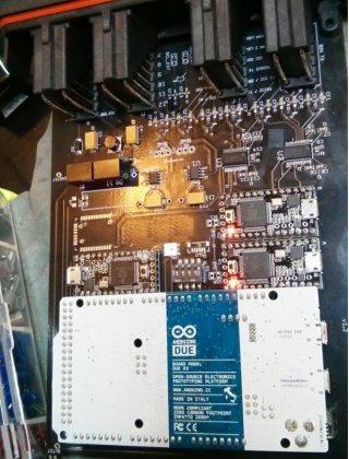
Here is a "completed" product for reference
Untitled.jpg


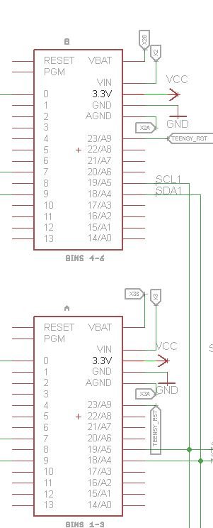
And schematic for reference
Capture.JPG
The VIN / AGND / BVAT are all tied together on the PCB with each their own net (maybe the problem)?
PIN 23 is linked on all the teensys without any resistors or anything but it isn't configured as an input or output pin so I thought it wasn't an issue.

I am powering the whole board and teensys with a 3.3v version of
www.adafruit.com/datasheets/tsr1.pdf‎

The arduino Due is being powered with the 9v version

The problem

around 90% of the time if I power the board, only the Due and ONE of the teensys (A on the board or the one on the bottom right) will fire up, leaving the other two teensys cold. this is a bad thing.
Sometimes I get lucky and the other teensys wake up and do their simple blink routine that I've programmed for now.

What I've Tried
Something very odd though... if I power (any single one of the teenys) via USB they will 100% of the time power up completely fine. If I then turn on the board power and unplug USB everything proceeds without issue.

I have tried connecting both and either of the 3.3v pins (on all of the teensys at the same time) just to see what would happen, basically the same results. Though sometimes it starts to look like it will be happy, it fails on the next power cycle.

I've measured voltage from the Teensys in both states of working and not working and I get a clean 3.28v on all of their 3.3v pins, even if their light is off.
I've measured mA and get 0.42mA from the 3.3v pins to ground on all the teenys in both states.


PLEASE PLEASE PLEASE PLEASE help :'( I'm running out of time. Thank you anyone that can help!!
 
Last edited:
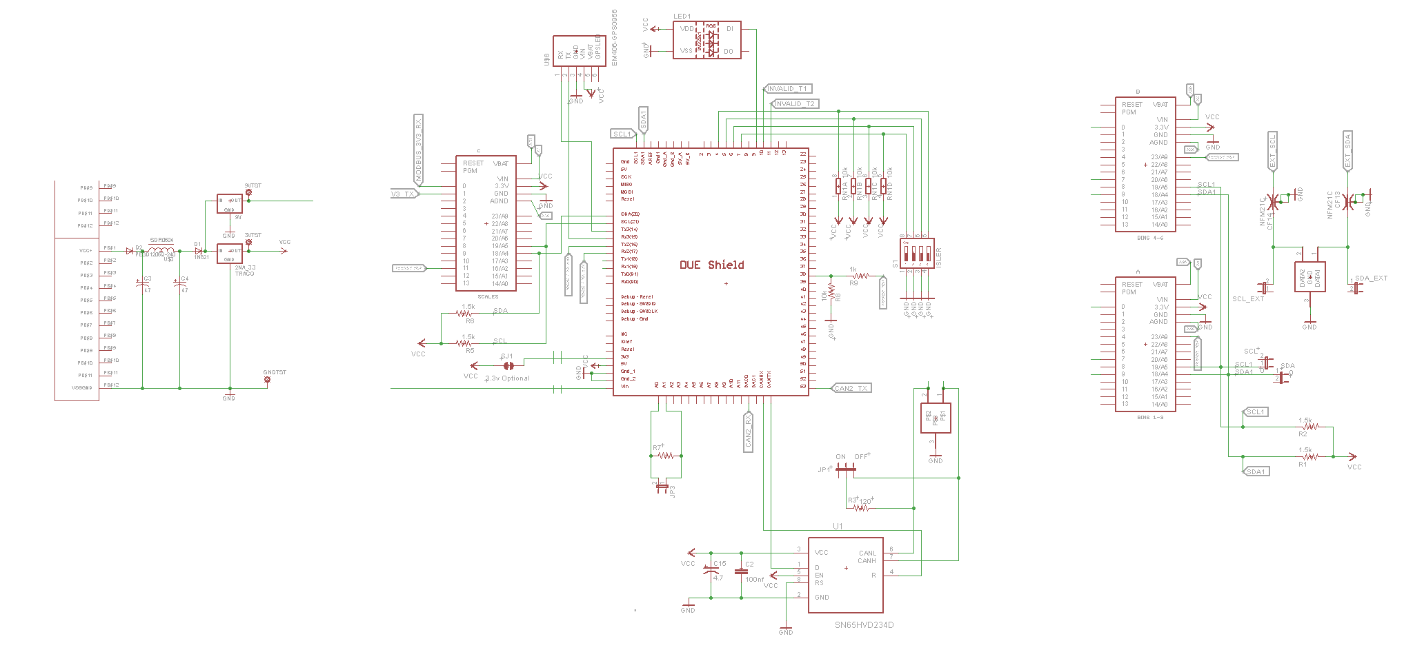
Maybe a complete schematic would be more telling than the little section. I cannot determine from your description what exactly is powered by what.
 
EyZBxoP.png


This is a little better, I'm not the greatest with schematics and this is basically my first project so I tried to make it simpler by omitting the unnecessary areas.
 
Last edited:
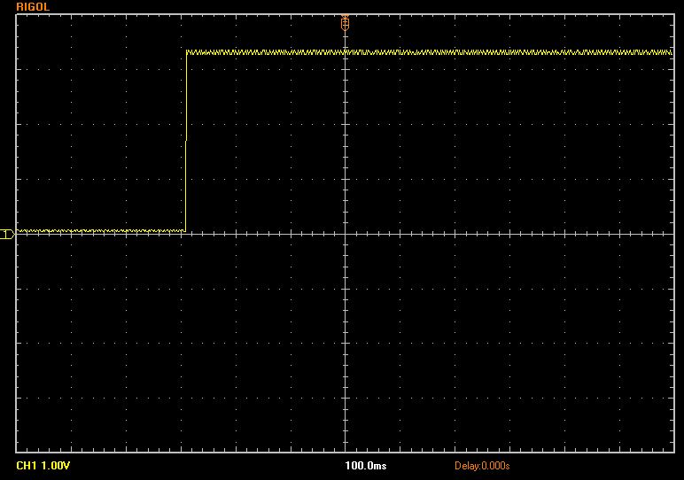
Do you have a digital scope? If so, could you capture the 3.3V power supply startup?

If you're pressed for time on an urgent project, first I'd cut the VBAT connections, and then I'd cut the 3.3V connection and kludge in a 7805 regulator from the 9V power to get a clean 5V, and run that to the VIN on each Teensy3 for their power.

I'd also agree with Headroom, that schematic fragment is worthless. All it shows is 2 wires connected between the I2C pins. The nets for the power are labels. They're not even the same names for the 2 Teensy3s shown, which doesn't match up with the statement that you're powering all the Teensy3s from an Adafruit power supply (also, the link to Adafruit's info is a 404 not found).

So with little info and with "running out of time", that's about the best I can suggest.
 
Power source is a Mastech bench power supply set to 12v and to allow plenty of amps, total system draw is 0.15 A


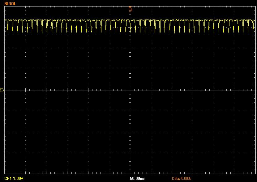
Started and running with just the power supply
GNbVqd2.jpg


100 ms per horizontal
1v for each vertical

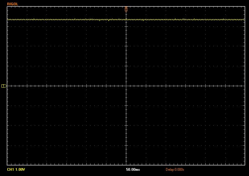
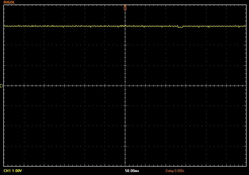
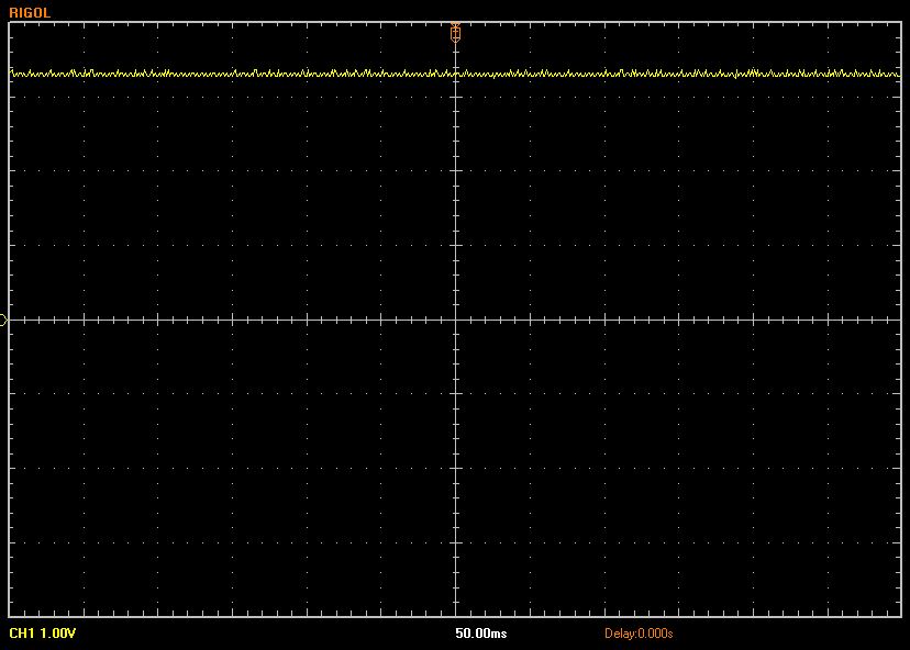
The following samples in order

Same show while USB is connected (50ms)
LSMawpJ.jpg


Started with USB and then turned on the Traco power
ByqNh07.jpg


Well now isn't this interesting? This is after unplugging USB. it's wavering all over the place
EbK8KlJ.jpg
 
Last edited:
Sorry looks like I'm spamming the images here.

But then after just a moment of dropping down like that it cleared up
4M5fjAX.jpg
 
Well, the power looks pretty good. I don't see any reason why those 2 Teensy3s ("A" and "B") would not start up.

The Teensy3s have labels X1, X1A, X1B on Teensy A; X2, X2A, X2B on Teensy B; and X3, X3A, X3B on Teensy C. Do those connect anywhere? I can't see anything else on the schematic with those labels. On the PCB, are the VIN, VBAT and AGND pins on every Teensy3 not connected to anything? (which should be fine)
 
I did that in Eagle so that they wouldn't connect anywhere, I misstated earlier that I made nets for them. I labeled them like that so they wouldn't auto net from the library I was using (provided by some kind soul here). So all three of those pins just stay sitting happy in the hole but don't go anywhere.

Here is something odd, when I just have USB plugged in the DUE is trying to draw power somehow. It's Vin is reading 1.5v... I don't see how that is possible. I'll check more, the LEDs on it a really really dim.. perhaps something I did is weird there. Just a note I am not using my SJ1 (3.3v optional) connection to the Due. But the Teensys will do this with or without the Due inserted. Also I removed the 9v Traco just for kicks and the problem still exists. After doing that the Due isn't getting voltage on it's VIN anymore though. I'm guessing the due is getting some light due to it's having i2c and some power coming in on the little status pins I have maybe.
 
Last edited:
Could it be something in software that is making them forget to wake up?


Teensy A & B & C are all basically the same:
Code:
#include <Wire.h>

const int ledPin = 13;
char incOne[8] = {0};
char incTwo[8] = {0};
char incThree[8] = {0};
byte serialData[13] = {0};
const int cR = 13;
byte serialChar =0;
byte i2 =0;
int j = 0;

// timer holds time since last update from scales
long serialMillis1 = 0;
long serialMillis2 = 0;
long serialMillis3 = 0;
//
long intervalTime = 5000;

int iAmStillAliveCounter = 0;


//values of scale data turned into ints for comparison
long intScale1 = 0;
long intScale2 = 0;
long intScale3 = 0;

byte debug = 0;

void setup() {
        Wire.begin(2);
        Wire.onRequest(requestEvent);
        Serial1.begin(9600);
        Serial2.begin(9600);
        Serial3.begin(9600);
        pinMode(ledPin, OUTPUT);
        pinMode(12, OUTPUT);
        delay(1000);
//        Serial1.println("Good Morning I am Serial 1 ");
//        Serial2.println("Good Morning I am Serial 2 ");
//        Serial3.println("Good Morning I am Serial 3 ");
}

//these functions are for setting appropriate bits in the serial data stream
void setFlag(int flagNumber){
   bitSet (serialData[12], flagNumber); 
}

void  clearFlag( int flagNumber){
   bitClear(serialData[12], flagNumber);
}

void loop() {
    
  
  unsigned long currentMillis = millis();
  
    digitalWrite(ledPin, HIGH);   // set the LED on
        
        if (Serial1.available() > 7) { 
            serialMillis1 = currentMillis;
            setFlag(0);
//            if (cR == Serial1.read()) {
                for (byte i=0; i<8; i++) {
                  serialChar = Serial1.read();
              	  if ((serialChar != 32) && (serialChar !=255)){
                      incOne[i2] = serialChar;
                      i2++;
                    }
       	        }
//            }
          i2=0;
        }  


        if (Serial2.available() > 7) { 
            serialMillis2 = currentMillis;
            setFlag(1);
//            if (cR == Serial1.read()) {
                for (byte i=0; i<8; i++) {
                  serialChar = Serial2.read();
              	  if ((serialChar != 32) && (serialChar !=255)){
                      incTwo[i2] = serialChar;
                      i2++;
                    }
       	        }
//            }
          i2=0;
        }  


        if (Serial3.available() > 7) { 
            serialMillis3 = currentMillis;
            setFlag(2);
//            if (cR == Serial1.read()) {
                for (byte i=0; i<8; i++) {
                  serialChar = Serial3.read();
              	  if ((serialChar != 32) && (serialChar !=255)){
                      incThree[i2] = serialChar;
                      i2++;
                    }
       	        }
//            }
          i2=0;
        }  


if (currentMillis - serialMillis1 > intervalTime)
{
//  Serial.println("Serial 1 Timeout"); 
  clearFlag(0);
}

if (currentMillis - serialMillis2 > intervalTime)
{
 // Serial.println("Serial 2 Timeout"); 
  clearFlag(1);
}

if (currentMillis - serialMillis3 > intervalTime)
{
//  Serial.println("Serial 3 Timeout"); 
  clearFlag(2);
}


    serialData[0] = intScale1 & 0xFF;
    serialData[1] = (intScale1 >> 8) & 0xFF;
    serialData[2] = (intScale1 >> 16) & 0xFF;
    serialData[3] = (intScale1 >> 24) & 0xFF;
    serialData[4] = intScale2 & 0xFF;;
    serialData[5] = (intScale2 >> 8) & 0xFF;
    serialData[6] = (intScale2 >> 16) & 0xFF;
    serialData[7] = (intScale2 >> 24) & 0xFF;
    serialData[8] = intScale3 & 0xFF;;
    serialData[9] = (intScale3 >> 8) & 0xFF;
    serialData[10] = (intScale3 >> 16) & 0xFF;
    serialData[11] = (intScale3 >> 24) & 0xFF;


     delay(130);

     
      if (serialData[12] > 0)
      {
        digitalWrite(ledPin, LOW);    // set the LED off
        iAmStillAliveCounter = 0;
      }  
      else{
         iAmStillAliveCounter= iAmStillAliveCounter+1;
      }
      
      if (iAmStillAliveCounter > 20){
        digitalWrite(ledPin, LOW);
        delay(50);
        digitalWrite(ledPin, HIGH);
        iAmStillAliveCounter = 0;
      }
      
     delay(130);

}

void requestEvent()
{
  Wire.write(serialData,13); // respond with message of 18 bytes
                       // as expected by master
}


The Due is basically the below

Code:
void setup(){
    Serial.begin(57600);
//    Serial2.begin(9600);
    delay(10000);
    Wire1.begin();
    Wire.begin();

    pinMode(13, OUTPUT);
    
//    pinMode(dipOne, INPUT);
    
    
   // LED SETUP
    strip.begin();
    strip.show(); // Initialize all pixels to 'off'
   //LED END
    
}
void loop() {


            Wire1.requestFrom(2, 13);    // request 18 bytes from slave device #2
                
            while(Wire1.available())    // slave may send less than requested
            { 
                  for (int i=0; i<13; i++){
                              teensyOne[i] = Wire1.read();               
                  }
            }

         
            Wire1.requestFrom(3, 13);    // request 18 bytes from slave device #2
                
            while(Wire1.available())    // slave may send less than requested
            { 
                  for (int i=0; i<13; i++){
                              teensyTwo[i] = Wire1.read();               
                  }
            }

        
            Wire.requestFrom(4, 32);    // request 18 bytes from slave device #2
                
            while(Wire.available())    // slave may send less than requested
            { 
                  for (int i=0; i<32; i++){
                              teensyModbus[i] = Wire.read();               
                  }
            }

Process data like a boss then output to CAN then loop
 
Last edited:
Well the below ended up being a lie... I let it sit for a bit and came back to play with it and I am back exactly where I was, Teensy A is happy as can be and the other 2 have derp'd out.

OK, to correct again... after pulling the 9V the system is basically working 90% of the time I turn it on now. Somehow even the i2c is working :/ I don't see how it could possibly be affecting the rest, it's so isolated? Is there something else I should do to the 9V - seems outside the scope of here (sorry).
 
Last edited:
I have removed the Delay lines in the front of each of the teensy programs and am at 99% working with hundreds of on and off flips. Perhaps this is a bug?
 
Looking at this again, I'm wondering if the I2C bus is getting stuck low?

Perhaps if Arduino Due isn't powering up, it might be holding both I2C lines low. Holding either line low means the busy is busy. Other devices wait for the lines to be released (go back high from the pullup resistors).

Next time it stalls, maybe measure the voltage on SDA and SCL? Or disconnect those 2 pins from one of the Teensy3s having trouble and see if it starts up reliably?
 
Thanks for taking another peek into this :)

I ran into the same problems though with the Due pulled off the board completely. I did measure the voltage of those lines with it off the board and found them to be sitting at 3.3v on the scope.
 
The madness continues, I worked on it over the weekend and I came to the conclusion that the delay has had no effect on the overall reliability. Though it seemed to be promising since at first it appeared that the three teensys woke up every time.

It still is the same pattern regardless of the Due being on the board:
Teensy A 100%
Teensy B 50%
Teensy C 25%

Any ideas please?
 
Last edited:
I have an engineering friend that suggested this:
"have you tried putting a 10k pullup or pulldown on the PGM pin? the teensies could be drifting into program mode sometimes. and by chance teensy A could have a slightly different tolerance and happens to stay out of "accidental program mode."

Any input on that?
 
Alight so some major sadness here

XN8gsuF.jpg


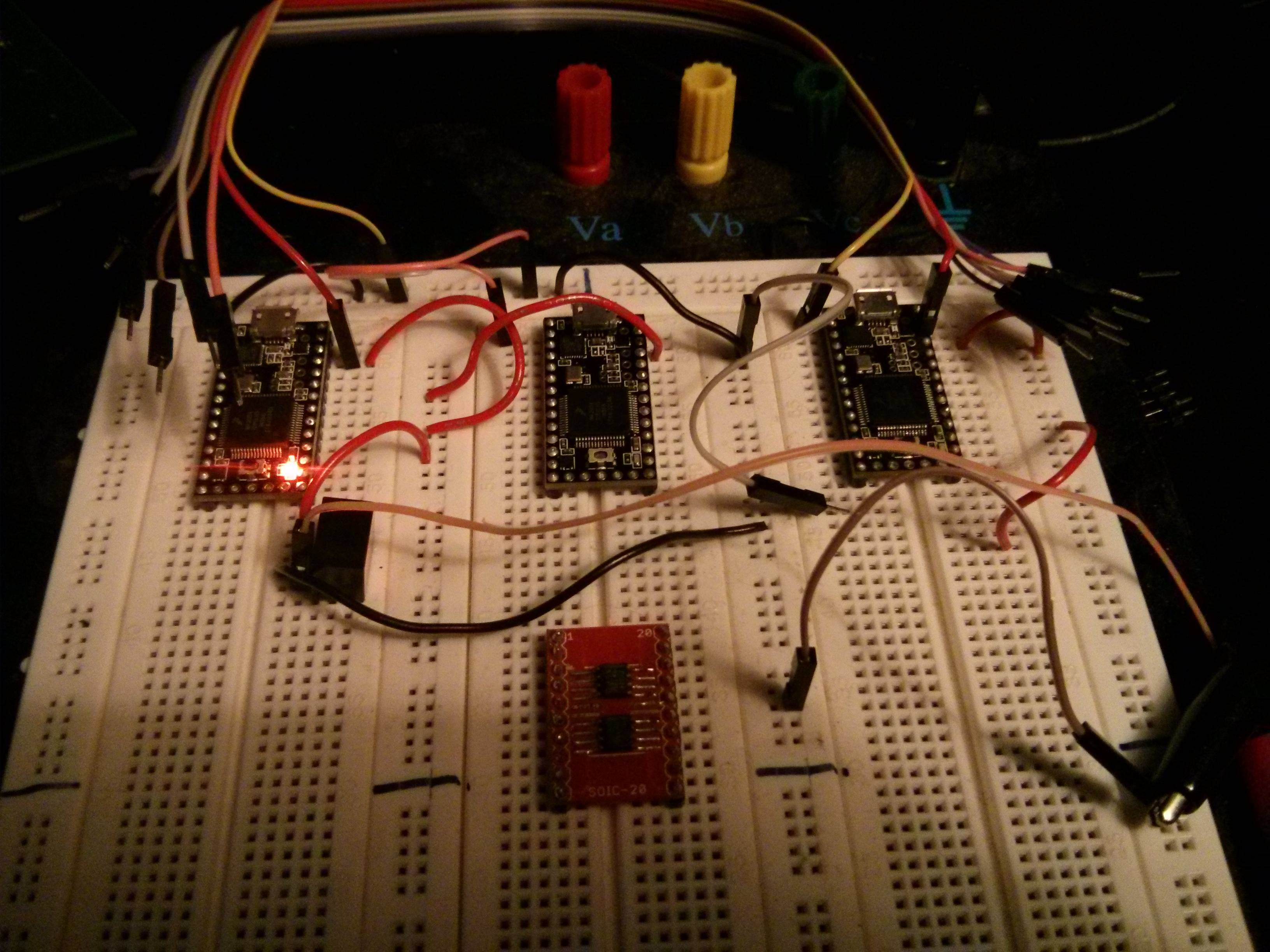
I put the teensys on a breadboard with ONLY the blink program installed ... and ONLY the 3.3v and the GND hooked up. and sadly... the same results. Can anyone suggest a replacement for the TRACO or other ideas?
 
As a quick sanity check, I just tried this same connection using a LM317 powered from 9 volts. All 3 boards definitely blink properly. I unplugged and reconnected the power at least a couple dozen times. All 3 started up correctly every time.

Here's a couple quick pictures.

lm317_1.jpg

lm317_2.jpg
 
How's this sound: I will send you the LM317 regulator and those 2 resistors, absolutely free. Just email me directly, paul at pjrc dot com, with your postal address. I'll put it in the mail tomorrow.

If the LM317 works, please mail that Traco part to me. If it's the cause of all this trouble, I'd like to do some tests on it.
 
Very kind of you, I happen to have one on hand and am going to ship out the first board with one in the place of the Traco. The 9V one is powering the Due just fine so it can stay. I am worried about excessive heat (my enclosure is sealed and very small) though so it would be nice to figure this out. I'll happily ship you a traco to test.

I'll mail to the address on the contact page today.
 
So, just to confirm, it's working with your LM317 chip too?

When I tested here, the LM317 got warm to the touch with 9 volts input and current to three Teensy3 boards.
 
Status
Not open for further replies.
Back
Top