
CharlieSears
Member
Taking the MK20DX128VLH5 and Nuvoton MINI54 for sale on the the Teensy store my plan was to integrate the teensy into a PCB for my application.
Looking over the schematic I had a few questions before I go forward.
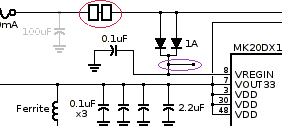
What are the unlabeled squares circled in red? I've seen this before as a voltage regulator.
EDIT: Whoops, apparently I can't read "A pair of pads are linked to join VUSB to VIN. For applications where external power is needed, these pads may be cut apart to isolate the board's VIN power from VUSB."
Is the purple circled line a 'typo'?
What inductance is necessary for the ferrite inductors listed throughout the schematic.
Has anyone taken the individual components and used them to 'build' their own Teensy based circuit before and have any advice?
The circuit I'm building is an (absurdly, unnecessarily high) 16 bit HID Joystick, I'll be using a TI ADS1256 24 bit ADC for low noise sampling and an LCD screen for information display.
I'm also correct in that I need a blank MK20DX128VLH5 and Nuvoton MINI54, and not the ATMEGA32U4 at all?
Looking over the schematic I had a few questions before I go forward.
What are the unlabeled squares circled in red? I've seen this before as a voltage regulator.
EDIT: Whoops, apparently I can't read "A pair of pads are linked to join VUSB to VIN. For applications where external power is needed, these pads may be cut apart to isolate the board's VIN power from VUSB."
Is the purple circled line a 'typo'?
What inductance is necessary for the ferrite inductors listed throughout the schematic.
Has anyone taken the individual components and used them to 'build' their own Teensy based circuit before and have any advice?
The circuit I'm building is an (absurdly, unnecessarily high) 16 bit HID Joystick, I'll be using a TI ADS1256 24 bit ADC for low noise sampling and an LCD screen for information display.
I'm also correct in that I need a blank MK20DX128VLH5 and Nuvoton MINI54, and not the ATMEGA32U4 at all?
Last edited:
")