IR Question not directly related to Teensy 3

Status
Not open for further replies.
I found a voltage regulator that will supply 3.3V 5A. It is the lowest cost one that is above 1.5A. Its dropout will be around 0.9V when everything is active so it will stop regulating when the batteries reach around 4.2V. That gives me a buffer for the batteries and keeps it simple not needing any extra resistors to configure the regulator

http://docs-asia.electrocomponents.com/webdocs/0aab/0900766b80aab29b.pdf

Been reading up on the darlington configuration and trying to find resistors with low beta values. I will try to test the darlington configuration this weekend
 
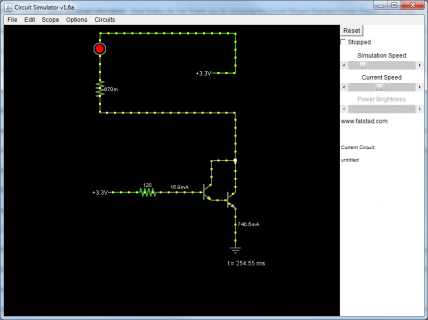
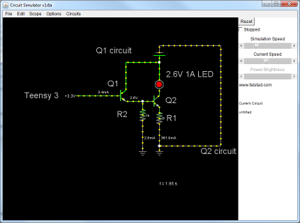
I found a circuit simulator. Do these numbers look about right? I created a darlington configuration

darlington.png
 
A Darlington has a larger drop than a single transistor -- its the sum of the VBE of the 'big' device (say 0.7) + VCE of the small one (say 0.3). Your LED could require up to 2.6 V -- so this won't work reliably from 3.3 V.

It can also be slow -- you can connect a R between B and E of the big device to speed it up -- use 100 ohm in your case (if you are trying to get peak LED currents of 1 A)

Alternatively, connect the C of the small device directly to the 3.3 V supply via a R. Calculate that R from (3.3 - 0.7) / I_LED * BETA. Say 1 A and beta = 20, so 52 ohm. Remember this will load the 3.3 V supply's regulator with 50 mA.

Now calculate your base drive R as (3.3 - 1.4) / 50 mA * BETA = 760 -- use 820 ohm.

If you are using linear regulators, then there is no energy advantage to driving the LED from their 3.3 V output as opposed to directly from the battery. However, the current would be more regulated, since it won't change with battery voltage.

Also, the R in series with the LED will dissipate about 1 W -- need a physically large one there (or use a parallel combination of four 1/4 W ones).

So, instead you could do:

directly connect small transistor (Q1)'s base to the T3 port (no R).
Q1's C --> battery
Q1's E -- > Q2 base (no R)
100 ohm from Q2 B to GND
Q2 collector directly to LED; LED to battery
R from Q2 E to GND.

R will have 3.3 - 0.7 -0.7 = 1.9 V across it; calculate the LED current from I_LED = 1.9/R_EMITTER.

Again be careful with power dissipation. With 2*4.5 V on battery = 9 V max, the current will be 1 A, and (at 100 % duty cycle) you'll dissipate a total of 9 - 2 (LED) = 7 V @ 1 A == 7 W. The R will take 2W, Q2 5W -- scale these numbers by duty cycle, and put a heatsink on Q2 !
 
I will build the circuit this weekend and also order some components to play with. My sound card doesn't work at 3.3V so need to figure something out there

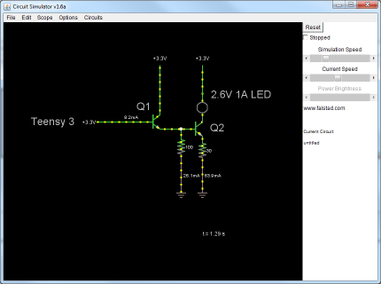
I created it in the simulator. It seems there isn't any power going through the LED in the simulator
Simulator URL http://www.falstad.com/circuit/
Simulation
$ 1 5.0E-6 0.09591894571091382 46 5.0 50
t 320 224 352 224 0 1 0.0 0.6881476784910641 10.0
t 400 240 448 240 0 1 0.6923513223019795 0.6947341404797529 10.0
w 320 224 256 224 1
g 400 368 400 384 0
162 448 160 448 224 1 2.6 1.0 0.0 0.0
R 256 224 192 224 0 0 40.0 3.3 0.0 0.0 0.5
R 352 128 352 80 0 0 40.0 3.3 0.0 0.0 0.5
r 400 240 400 320 0 100.0
g 448 368 448 384 0
r 448 256 448 320 0 30.0
w 448 320 448 368 1
w 400 320 400 368 1
w 352 128 352 208 0
w 352 240 400 240 2
x 300 198 332 204 0 24 Q1
x 62 232 160 238 0 24 Teensy 3
x 466 246 498 252 0 24 Q2
x 468 171 604 177 0 24 2.6V 1A LED
R 448 128 448 80 0 0 40.0 3.3 0.0 0.0 0.5
w 448 128 448 160 0


darlington2.png
 
Run the LED directly from battery instead of from the 3.3 V supply -- that will reduce that supply's load and size.

It might be possible to increase the 100 ohm to 1k; it all depends on speed you need to turn the LED off at.
 
I fixed it, thank you. Didn't know there was a difference between a voltage source with 1 output and voltage source with 2 outputs in this app
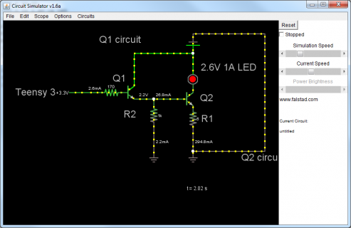
Changing R1 in the simulator to 5 ohm and R2 to 1k shows Q2 circuit going at lightning speed.


$ 1 5.0E-6 0.09591894571091382 46 5.0 50
t 320 224 352 224 0 1 -1.7000000000000002 0.6661567681358074 10.0
t 400 240 448 240 0 1 0.14852093290504031 0.7242761217250777 10.0
w 320 224 256 224 1
g 400 368 400 384 0
162 448 160 448 224 1 2.6 1.0 0.0 0.0
R 256 224 192 224 0 0 40.0 3.3 0.0 0.0 0.5
r 400 240 400 320 0 1000.0
g 448 368 448 384 0
r 448 256 448 320 0 5.0
w 448 320 448 368 1
w 400 320 400 368 1
w 352 128 352 208 0
w 352 240 400 240 2
x 300 198 332 204 0 24 Q1
x 62 232 160 238 0 24 Teensy 3
x 466 246 498 252 0 24 Q2
x 468 171 604 177 0 24 2.6V 1A LED
w 448 128 448 160 0
v 448 80 448 128 0 0 40.0 5.0 0.0 0.0 0.5
w 448 80 624 80 0
w 624 80 624 368 0
w 624 368 448 368 0
w 448 128 352 128 0
x 469 297 499 303 0 24 R1
x 327 286 357 292 0 24 R2
x 567 392 669 398 0 24 Q2 circuit
x 267 103 369 109 0 24 Q1 circuit

darlington3.png
 
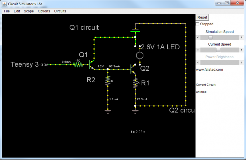
It seems when I remove the LED from the circuit the amps going into Q1 increases to almost 40 mA so that will blow up the Teensy
If I add a 170 ohm resistor between the Teensy and Q1 base and the LED blows the Teensy seem to be safe

LED alive
darlington4.png


LED dead
darlington4 deadled.png
 
@taskman re your code in post#1

Do you really need to turn IR on/of for 8 uSecs? If no, I recommend using PWM on the relevant pins and just enabling/disabling the PWM on those pins as needed. his means that you code wont be blocking. I am not sure if laser tag is a standard and if it specifies a 8 uSecs toggle. If not you should consider using IR modulated at between 30-60KHz, particularly if you are operating outdoors, otherwise you will get big solar interference. These modulation frequencies were originally chosen as the Sun emits at a lower level in this range. We are always looking to add new IR protocols to our project and will look into laser tags to see if there are any common standards.

If you change to using a modulation frequency, then pick one that isn't being used by common TV remote controls. Also, you are likely to experience big issues with reflection/bounce indoors. Although, I haven't seen a perfect solution for this, there are ways of mitigating this problem. Let us know the details of any issues and we may be able to help.

@pjrc - Does teensy V3 have a similar granularity of 4 uSecs as the standard Arduinos, using delay microseconds?. If not V3 may open up some new possibilities for our own IR projects. We have also been following your efforts with faster serial via USB and hope to play with your ideas when we get some time. We have a crowdfunding project and will add Teesnsy V3 as one of the new platforms for backers to vote on for inclusion.

For anyone interested in IR you can find out about our project on http://igg.me/at/AnalysIR/x/3752156

Chris
 
Hi

Thank you for your input. I haven't had time to look at my range code or the IR code for a couple of weeks while I have been waiting for the parts for the range setting and working on my sound. I am using TSOP1156 (http://www.vishay.com/docs/82006/tsop11xx.pdf) that needs signals at 56 kHz. The 8 uSec time between pulses seem to give me the least amount of errors, but I am currently developing indoors and haven't tested it in direct sunlight yet. I am basing my protocol on the protocol of the current laser tag weapons that we own, but with a twist. They seem to require around 6 uSec between pulses to work correctly.

I actually created a new protocol, well I think I did :) Normally, what I have seen, IR protocols only use the high to transmit values with then a constant pause between pulses. I use the high and the low, but I also have a separator between the parts of my message, e.g I might send player ID of 1 and I would just pulse a 600 (600 = high in my case). Normally protocols would send a full byte so they would send 00000001. I just send 1 with a separator. The calculations that I did showed that only when you reach the 200+ players does my protocol start taking longer to transmit. I think the world record for the maximum number of players has been 400+ so you don't normally have that many players. Actually I am busy packing for a game at 14:00 for 5 players. The other thing my protocol allows is 65000 players, 65000 different teams, 65000 different damage modifiers and so on. Other companies have many many limits. If my processor gets more memory some day I can change from uint16_t to maybe something bigger and bam I can handle millions of players. Not that I need it. Maybe when I am done and I see I have memory to spare I will change to something bigger than uint16_t just so I can say I can handle a couple million players, great for marketing :)

I also switch off interrupts while I transmit so that I can make sure the message gets to the other side. We have noticed with the guns we use in our business that you shoot and the message just doesn't arrive on the other side or the wrong message arrives on the other side. We have seen that when player 1 shoots player 2, player 1 could even change player 2's team, because of an error in the message. We have seen some strange things where a player shoots another player and the message gives the other player unlimited lives. Ofcourse I still have a long way to go and alot of testing still needs to be done. Hopefully I won't have the same problems.
 
OK

First thing is the TSOP you are using is effectively EOL and you should consider something like TSOP38456, TSOP58456 or TSOP31456 instead.

Second, it seems the 8 usecs you mention is half the period of the modulation frequency, which works out at 62.5 KHz. I believe 9 uSecs is closer for 56KHz ( works out at 55.5KHz & may improve accuracy). I suggest you study up on the make-up of IR signals before sending more time on it as you will hit a lot of dead ends before you get it right (if at all). A good place to look is sb-projects (google sb-ptoject IR) - it goes thru all the basics.

When designing your protocol you need to look at and optimise for the following:
- modulation frequency
- duty cycle
- timings for headers, Marks & spaces.
- encoding for bits (pulse width or mancester encoding)

Then you need to take your conclusions and match them up with the right IR receiver ( looking at AGC, Half intensity angle). The TSAL6100 you have already is probably the best for range and narrow angle (+/- 10 Deg = 20 deg )

I suspect you will definately hit problems in sunlight without appropriate mitigation for Sun outdoors and also reflection/bounce indoors.

Another, way to increase numbers could be to use different modulation frequencies & different bit encoding schemes for different teams - would avoid friendly fire also :) during the game.

Best of luck with your efforts & let us know if you hit specific issues with IR & we will try to help out.

(I will have to read up on IR use in laser tag, as I am curious now)

Chris

--------------------------------------------------------------
For anyone interested in IR you can find out about our project on http://igg.me/at/AnalysIR/x/3752156
 
I installed the mosfets (http://www.vishay.com/docs/91322/91322.pdf) and resistors this week and I have been trying to figure out what is wrong. It seems I am not getting full power from the LED. I compared the light with the light from our current laser tag guns. Their light makes a nice completely filled white circle. Mine makes a circle with little black spots. Think of a flash light with a low powered battery. I added extra wires between the voltage regulator breadboard positive and negative to the main breadboard positive and negative in the hopes that I don't lose power through wires as can be seen on the left side of the main breadboard http://www.flickr.com/photos/92380311@N04/9263204287/. I also added alot of extra wires between the positive and negative lines of the main breadboard


My voltage regulator supplies around 3.7V to the circuit. I measured it in 3 different places to make sure I get the correct power
Here I measure between the battery negative and the Team LED
http://www.flickr.com/photos/92380311@N04/9263204287/
http://www.flickr.com/photos/92380311@N04/9263204535/
http://www.flickr.com/photos/92380311@N04/9263204737/

Here I measure between the battery negative and the IR LED positive pin. IR LED is off at this point. When I measure across the IR LED when it is flashing I see around 300mV with my multimeter
http://www.flickr.com/photos/92380311@N04/9265980862/
http://www.flickr.com/photos/92380311@N04/9265981220/

Measure between the battery negative and a wire going into the breadboard
http://www.flickr.com/photos/92380311@N04/9265980196/
http://www.flickr.com/photos/92380311@N04/9265980746/


This is my mosfet setup. Looking at the left mosfet, the yellow wire is from the Teensy 3 going into a resistor. I tried no resistor up to 460 ohm and nothing changed. The resistor goes into the Gate of the mosfet. The white wire comes from the negative of the IR LED and goes through a resistor into the drain. I also tried no resistor here and still didn't get full power. The black wire goes from source to negative/ground of the breadboard and then to the battery
http://www.flickr.com/photos/92380311@N04/9265981092/

I can't measure the Amps. When I place my multimeter in the circuit the light doesn't come on and 0 amps are displayed on my multimeter. I don't know if it is because my multimeter can't handle the fast switching or if there just isn't enough Amps and the multimeter is consuming what ever is available.

When I measure the Voltage with my multimeter I see around 300mV on the meter. I tried using my oscilloscope and I also only see around the same amount of mV
http://www.flickr.com/photos/92380311@N04/9265981576/

I ordered a different mosfet (http://docs-asia.electrocomponents.com/webdocs/0791/0900766b807910ef.pdf) with a lower Rds. I read that might make a difference. If that doesn't work I will try the mosfet driver (http://docs-asia.electrocomponents.com/webdocs/0c91/0900766b80c91a9c.pdf).
 
Sorry
I cant make much sense of your setup. When debugging a circuit like this, I sometimes try to isolate the part I am testing so as to remove any unintended confusion with other parts of the circuit. Maybe just set up your LED driving circuit on its own breadboard and then test.

If you are looking to drive high current thru your IR LED, I did a bit of searching and found the guys over at Miles Tag (http://www.lasertagparts.com/mtdesign.htm) to be the experts they are driving very long range IR using current, special LEDs and most importantly good quality Optics (lenses). I suggest you read the whole site as it seems to be the source. They also publish their own IR protocol and have an Arduino section as well.


Best of luck with your project.
---------------------------------------------------------------------------------------------------
Support our project for AnalysIR - IR Decoder & Analyzer GUI(Arduino & Raspberry Pi) by visiting http://igg.me/at/AnalysIR/x/3752156
 
Good idea. I will move just the IR to its own breadboard and see how it goes

I have actually been busy with my gun development since December 2012 I believe. I have written over 10 000 lines of code if you combine the battlebox, headset, gun and Android controller code. Miles Tag website was one of my resources I used in the beginning. I bought lenses from the same people they get their lenses from and I am using the IR LED that they recommend and sell. I also reversed engineered the IR signal of our current guns that we bought to see what they do and that is where I learnt the trick of using the High and Low to encode the commands. My messages are sent correctly. I have implemented more than 70 commands already and have some abilities built into the guns that I haven't seen anywhere else.

I believe it is now just hardware issues and that is where you guys come in because I am a junior when it comes to electronics :)

Thank you for your help
 
56KHz... ok. most consumer IR uses 38KHz. But either is OK. - - the IR receiver as a filter tuned for one or the other. I think most 56KHz IR is in the super high end home theater gear - from the EU.
The IR receiver needs to be optically shielded from ambient light from windows and ceiling. Must have an optical filter to reduce ambient light too.
It needs Vcc that is super clean - decoupled with a low value resistor, a beefy electrolytic and a good RF bypass - to get rid of all noise on Vcc.

Consumer Ir I've worked with needs carrier on/off times (bit times) corresponding to about 1Kbps - due to the filter bandwidth width in the IR receiver. And most IR codes have a long start bit - like carrier-on for several mSec before data.

Miles (I work with that) uses much more sophisticated modulation methods and consumer IR - as the Vishay is intended for.
 
With 6.5V I am not blowing the LED and I am getting the brightness I am after. It is probably reducing the life of the LED, but I am still only reading a couple hundred mV over the LED. This is most likely why the guns we have use 7.2V NiMh, charged to 8.5V or so. Probably also because they use old PIC micro chips that probably need 5V. They probably push the full voltage through the LED as what I am doing now. I am going to increase my voltage to 9.9V and see if it blows the LED. Charging up my whole pack before I add the extra one so can only test tomorrow night again when it is nice and dark and easy to test IR. I should get my mosfet driver in about a week and I will see how that goes. I ordered a non-inverting. Hopefully that is right. Reading on other forums it seems inverting you need to switch the PWM signal around

I am not allowed to take the batteries lower than 2V so minimum of 6V then for 3. If I setup my regulator to supply 5.7V I will probably be very close to the 6V switch off, but 5.7V is too much for the Teensy and probably the sound card. I am thinking to just add a diode to reduce it the little bit that is needed. The extra voltage might also give me full volume on the sound card, seems it doesn't like 3.7V much, can only get to 15/30 volume
 
I am using this driver now http://docs-asia.electrocomponents.com/webdocs/0c91/0900766b80c91a9c.pdf and it doesn't seem to make a difference. I also moved the circuit to its own board so that there is very little that could cause a problem, still no difference. I will try some of my old basic PWM test code that I use for other things tonight to see if it isn't maybe something to do with the code

I tried increasing my delay time between pulses from 8 to 18 and no difference.

What is strange is if I use the 3.5V from the regulator and I connect that to the LED mosfet and to the driver I do get light, but if I connect 6.6V (batteries directly) to the driver and still 3.5V to the LED mosfet nothing happens. I thought maybe the gate voltage isn't allowed to be more than the drain voltage so I connected 6.6V to the driver and to the mosfet and still nothing happens. I then connect 3.5V again and I have light so the LED doesn't blow when I do this. The battery is the same one that powers the regulator so everything is grounded correctly I believe. I even moved the positive and negative of the battery to the mini circuit to make sure I don't have some grounding issue, that didn't help, still no light at 6.6V

I still can't measure the amps. When I have the ammeter between the LED and the mosfet the LED doesn't switch on and I get no reading

Maybe I should take a video of what I am doing or go see an electronics workshop or maybe go see the guys at the hacker space. I must be doing something wrong, should have blown the LED by now with all the power I am passing through it. Actually tried 3 different LED's from the pack to make sure I didn't maybe damage the LED with the power, no difference
 
An ohm meter will tell you if the LED failed.
If you have a common low cost digital meter, it will have volts and amps. But since the LED is pulsed, and the current flow is not DC, the meter will try to average.
 
I do have a low cost $100 meter so to really measure what is going on I need a high cost Fluke or something like that
My oscilloscope should give me an idea of the voltage at least, but not the amps?

I am starting to think to go on with the rest of the project so that I at least have something and then try and fix these kinds of problems later on.
 
Status
Not open for further replies.
Back
Top