Teensy3.0 and Wiz812MJ

Status
Not open for further replies.
@headroom
from the docs http://www.pjrc.com/teensy/td_libs_Ethernet.html
Ethernet.begin(mac, ip, gateway, subnet);
Initialize the Ethernet library and hardware. "mac" and "ip" are required. "gateway" and "subnet" are optional.
If I just use mac, the code doesnt compile.
My network accepts static IP and dynamic, half my pc's are static half dynamic, and even if the IP was conflicted, the IP should be set in code and be reported via the serial monitor anyway shoudln't it?
@Paul, I'm asuming it is fucked, hence buying a new one at the weekend and only using that once I knew my power was at 3v
@stevech how can I assume my wiring is correct when the most basic example fails to work? But I dont know how to R/W a register as I've never play with this kit before... Do you have code I could run as a check?

What is the maximum wattage of PSU I should use with this setup? Initially I had a 10a 5v supply, and I get the feeling that the regulators are trying to drop the voltage of the whole power output, I was under the impression that they should only draw what they need, certainly teensy3 doesnt mind being on a 10a supply, but I presume I am wrong here? Given that I've killed 2 of your adapter boards, or certainly the regulators thereon...
 
Also given that I have 2 power suplies and no reset, should the boards be powered in a particular order?
I can't power them on together as teensy is via usb, and the wiz via a wall wart.
 
Correct, I was posting from work on my iPhone and did not remeber things as I should have. Sorry for the confusion.

However, if you only use "Ethernet.becin(mac, IP) what will be compiled for and runnig on the Arduino is the DHCP code/client. The IP address is the IP address of your router that is DHCP enabled, meaning it runs a DHCP server.
The Client running on the Arduino will request an IP address from your router and you router should respond with an IP address from the pool it has available (what that is depends on the router configuration). That is usually the IP address that is reported on the serial monitor. If the DHCP request fails then there will be no IP address to report on the Serial on monitor, but that obviously depends on how the sketch is written. that's why I suggested Zoomcat's sketch as I know what that does ;-)

As long as the wattage of your PSU is enough and the voltage it supplies to the Arduino is within the spcified range the Arduino should be OK. It will only draw the current it needs.

As should be clear by now, WIZ812MJ adapter accepts 5V input and has an on-board linear low droipout voltage regulator that will make sure that the WIZ812MJ is supplied with the correct 3.3V. Unless that regulator is broken, which should be very easy to verify with a simpe multimeter, there is no reason that the WIZ812MJ should be broken. However, you may want to verify what output the wall wart is providing. If the voltage is too high for the regualtor on the Adapterboard (6V according to the spec sheet) it may in fact be damaged.

If you can't power the boards together I would try to first power the Arduino and perhaps put a "delay()" in your setup() code to allow enough time for you to power up the WIZ812MJ.
 
Last edited:
However, if you only use "Ethernet.becin(mac, IP) what will be compiled for and runnig on the Arduino is the DHCP code/client. The IP address is the IP address of your router that is DHCP enabled, meaning it runs a DHCP server.
Really? I thought it would set that IP to the device manually, and setting it to the routers address still gives 0.0.0.0

The adapter has only been powered via a v5 regulated supply, and currently a wall wart that meters 4.5V, and the regulator meters 3.3 so is working correctly, I could now go back to powering the teensy via the same wall wart now however...
As you can tell I've been trying to narrow down what could be the problem and failing!
 
Using the zoomcat sketch from here http://forum.arduino.cc/index.php?PHPSESSID=562e1r6d1jen465bs3e4q0i744&topic=57972.0;wap2
I get this error
Code:
sketch_jul16b.ino:14:17: error: no matching function for call to 'Server::Server(int)'
sketch_jul16b.ino:14:17: note: candidates are:
In file included from C:\Users\cat\Desktop\arduino-1.0.4\libraries\Ethernet/EthernetServer.h:4:0,
                 from C:\Users\cat\Desktop\arduino-1.0.4\libraries\Ethernet/Ethernet.h:8,
                 from sketch_jul16b.ino:8:
C:\Users\cat\Desktop\arduino-1.0.4\hardware\teensy\cores\teensy3/Server.h:6:7: note: Server::Server()
C:\Users\cat\Desktop\arduino-1.0.4\hardware\teensy\cores\teensy3/Server.h:6:7: note:   candidate expects 0 arguments, 1 provided
C:\Users\cat\Desktop\arduino-1.0.4\hardware\teensy\cores\teensy3/Server.h:6:7: note: constexpr Server::Server(const Server&)
C:\Users\cat\Desktop\arduino-1.0.4\hardware\teensy\cores\teensy3/Server.h:6:7: note:   no known conversion for argument 1 from 'int' to 'const Server&'
C:\Users\cat\Desktop\arduino-1.0.4\hardware\teensy\cores\teensy3/Server.h:6:7: note: constexpr Server::Server(Server&&)
C:\Users\cat\Desktop\arduino-1.0.4\hardware\teensy\cores\teensy3/Server.h:6:7: note:   no known conversion for argument 1 from 'int' to 'Server&&'
sketch_jul16b.ino:14:8: error: cannot declare variable 'server' to be of abstract type 'Server'
In file included from C:\Users\cat\Desktop\arduino-1.0.4\libraries\Ethernet/EthernetServer.h:4:0,
                 from C:\Users\cat\Desktop\arduino-1.0.4\libraries\Ethernet/Ethernet.h:8,
                 from sketch_jul16b.ino:8:
C:\Users\cat\Desktop\arduino-1.0.4\hardware\teensy\cores\teensy3/Server.h:6:7: note:   because the following virtual functions are pure within 'Server':
In file included from C:\Users\cat\Desktop\arduino-1.0.4\hardware\teensy\cores\teensy3/Stream.h:24:0,
                 from C:\Users\cat\Desktop\arduino-1.0.4\hardware\teensy\cores\teensy3/HardwareSerial.h:54,
                 from C:\Users\cat\Desktop\arduino-1.0.4\hardware\teensy\cores\teensy3/WProgram.h:16,
                 from C:\Users\cat\Desktop\arduino-1.0.4\hardware\teensy\cores\teensy3/Arduino.h:1,
                 from C:\Users\cat\Desktop\arduino-1.0.4\libraries\SPI/SPI.h:15,
                 from sketch_jul16b.ino:7:
C:\Users\cat\Desktop\arduino-1.0.4\hardware\teensy\cores\teensy3/Print.h:22:17: note: 	virtual size_t Print::write(uint8_t)
In file included from C:\Users\cat\Desktop\arduino-1.0.4\libraries\Ethernet/EthernetServer.h:4:0,
                 from C:\Users\cat\Desktop\arduino-1.0.4\libraries\Ethernet/Ethernet.h:8,
                 from sketch_jul16b.ino:8:
C:\Users\cat\Desktop\arduino-1.0.4\hardware\teensy\cores\teensy3/Server.h:8:16: note: 	virtual void Server::begin()
sketch_jul16b.ino: In function 'void loop()':
sketch_jul16b.ino:33:24: error: 'class Server' has no member named 'available'
sketch_jul16b.ino:33:8: error: cannot declare variable 'client' to be of abstract type 'Client'
In file included from C:\Users\cat\Desktop\arduino-1.0.4\libraries\Ethernet/EthernetClient.h:5:0,
                 from C:\Users\cat\Desktop\arduino-1.0.4\libraries\Ethernet/Ethernet.h:7,
                 from sketch_jul16b.ino:8:
C:\Users\cat\Desktop\arduino-1.0.4\hardware\teensy\cores\teensy3/Client.h:9:7: note:   because the following virtual functions are pure within 'Client':
C:\Users\cat\Desktop\arduino-1.0.4\hardware\teensy\cores\teensy3/Client.h:14:18: note: 	virtual size_t Client::write(uint8_t)
C:\Users\cat\Desktop\arduino-1.0.4\hardware\teensy\cores\teensy3/Client.h:15:18: note: 	virtual size_t Client::write(const uint8_t*, size_t)
C:\Users\cat\Desktop\arduino-1.0.4\hardware\teensy\cores\teensy3/Client.h:16:15: note: 	virtual int Client::available()
C:\Users\cat\Desktop\arduino-1.0.4\hardware\teensy\cores\teensy3/Client.h:17:15: note: 	virtual int Client::read()
C:\Users\cat\Desktop\arduino-1.0.4\hardware\teensy\cores\teensy3/Client.h:19:15: note: 	virtual int Client::peek()
C:\Users\cat\Desktop\arduino-1.0.4\hardware\teensy\cores\teensy3/Client.h:20:16: note: 	virtual void Client::flush()
C:\Users\cat\Desktop\arduino-1.0.4\hardware\teensy\cores\teensy3/Client.h:12:15: note: 	virtual int Client::connect(IPAddress, uint16_t)
C:\Users\cat\Desktop\arduino-1.0.4\hardware\teensy\cores\teensy3/Client.h:13:15: note: 	virtual int Client::connect(const char*, uint16_t)
C:\Users\cat\Desktop\arduino-1.0.4\hardware\teensy\cores\teensy3/Client.h:18:15: note: 	virtual int Client::read(uint8_t*, size_t)
C:\Users\cat\Desktop\arduino-1.0.4\hardware\teensy\cores\teensy3/Client.h:21:16: note: 	virtual void Client::stop()
C:\Users\cat\Desktop\arduino-1.0.4\hardware\teensy\cores\teensy3/Client.h:22:19: note: 	virtual uint8_t Client::connected()
C:\Users\cat\Desktop\arduino-1.0.4\hardware\teensy\cores\teensy3/Client.h:23:11: note: 	virtual Client::operator bool()

Now I'm a begineer at arduino, and thius ethernet example, a painful beginner!
But there are a mix of / and \ in the library path, so I presume theres an issue there?
 
Can't really comment on your error report without sitting at my home machine. I'll post some code some time tonight that I know compiles as i've i've tested it many times.
Hang in there!
 
Here is a link to the Zoomcat Ethernet Sketch that compiles fine under Arduino 1.0.4/5 and runs fine on my Teensy++2 using a WIZ812MJ and the standard Ethernet library. It also runs fine on the Teesny3 with the WIZ820io using an Ehternet library modified to work with the W5200 chip on the WIZ820io.

https://dl.dropboxusercontent.com/u/52985275/Zoomkat_Ethernet.ino
Right click and download linked file as.. or whatever a Windows equivalent is.

You compilation errors look quite suspicious. You may want to try a fresh Installation of Arduino 1.0.5 and Teensyduino 1.15.
 
Last edited:
Thanks for your help!
It also runs fine on the Teesny3 with the WIZ820io using an Ehternet library modified to work with the W5200 chip on the WIZ820io.
Whats/where is this modified library?

I was moving back to 1 psu, foolishly I was using the unregulated wallwart which decided that it wanted to put out 7.5v rather than the 4.5 it had been and has fried both teensy and wiz board :\

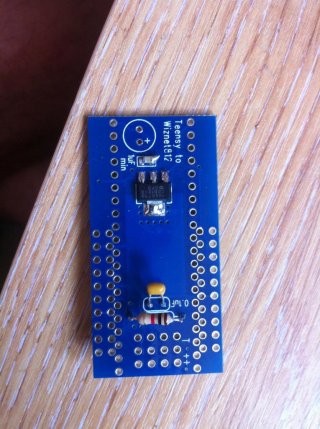
So I've started from stratch again, soldered up a new adapter board, plugged that into 5v and the voltage drop isn't to 3.3v its 4.5v, this is with no load, just the adapter. Should it not give 3.3v in this situation, or does it need a load to give 3.3, or have I killed it while soldering it in, it took a lot of heat to get the solder to melt on the tab, in the uk we dont have lead solder, and I'm all out of my stock from when we did, so solder here is just shit, it would melt but just ball up on the tab, despite much flux. This is the 3rd of 4 adapters I bought, the others are now just passing through 5v, so I will try and get new regulators for them.
But I think this is probably the root of my problem with odd voltages.
Have I kiiled the regulators?

I'll try the code when I recieve a new wiz board, and if you can confirm my fears above! After that I think I will give up, 3 wiz boards down and a teensy, is just too much!
 
So I've started from stratch again, soldered up a new adapter board, plugged that into 5v and the voltage drop isn't to 3.3v its 4.5v, this is with no load, just the adapter. Should it not give 3.3v in this situation,

Something is wrong! It should be 3.3 volts. The MCP1825 does not require a load for proper regulation.

As a sanity check, I just tried on my board (the photos in message #2) with the WIZ812 removed. One side of the MCP1825 has 5.1 (the voltage from a USB hub I'm using) and the other size measures 3.28 volts.

If you're seeing 4.5 volts on the output side of the MCP1825, then something is very wrong. DO NOT plug in the WIZ812 module. You need the regulator producing proper 3.3 volts to use the WIZ812.

Ok Thanks for that!
This was my fear, the first board I made I didn't check till after adding the wiz board and not getting anything working. (so wiz1 presumed dead)
The second did 3.3 until the wall wart put out 7 and now also does 4.5 (wiz2 dead)
The third I have just soldered up and checked and does 4.5, dont have another to kill yet, so I need to know, whats going on?
Can overheating while soldering kill the regulator? How long should it take to heat, its several seconds on full heat off my soldering iron to get the tab done.
I have one more regulator to try...
 
Those regulators should take high temperatures. The Vin and Vout leads don't have a large mass and should solder OK in 2 or 3 seconds. But then I've not used lead-free.
The large tab would take longer of course, depending on the PCB copper mass size.

Sounds like there is something else going on here. Grounds, measurement techniques, regulator wiring.

I make a habit of not plugging in electronics modules until the Vcc/Vdd is tested and known good.
 
So I've just soldered a new board, even managed with minimal heat, only connected the 5v supply absolutely no other circuit here, and the output reads 4.5v.
The psu is a regulated 5v 3.4A supply.
Attached is a picture of my dodgy soldering.
I can see me fucking up a couple of boards, but this is really not right, it is my first time soldering smd stuff, but I've been soldering leads and larger components for many years, and while I'm not the worlds best solderer, things have always ended up working!
I can only now make my own regulator from bigger components I suppose...

IMG_1475.jpg
 
Actually before I waste any more time/money on this, do you think I can replace the serial control on the octows library with ethernet, as thats what I'm planning to do here, ie does this network chip have enough bandwidth to drive 800 LED's ?
 
You NEVER give up ;-)

Lead Free is fine, but it takes higher temperature. I had removed the components from one of my WIZ812 adapter baords ad resoldered new parts last night wirth lead free (I don't use leaded for anything). You want to heat up the tap for 2-3 seconds before attempting to add solder.

Paul and stevetech already have ansewred the regulator related questions. I can only agin recommend the little swithched DC/DC converters from Traco Power particularly the TSR-1 series. You can stick these right into a breadboard, or solder these into a vero board as these have 0.1" spacing. No addtional components needed.
$14 at Mouser and while I have not checke I bet you can get these at Farnell in the UK as well.

Also, for the WIZ812MJ you don't need the modified library, only for the WIZ820io. As I've mentioned before, once you've streighened out the electrical problems you may want to start with a clean installation fo eeverything. The Arduino Sketch I've provided should run out of the box.
 
As to replacing the serial in the OctoWS2811, the answer is NO. AFAIK that library is written to interface with a specific, very popular, LED chip and it's strict timing requirements. Thus the name octoWS2811There is absolutely no connection between the Ethernet protocol and how these chips are driven!

Question: Why would you want to replace that with Ethernet ?
 
My reasoning for ethernet is, the ethernet data becomes serial in the teensy anyway, so as long as its formated correctly, it should be fairly simple to swap round, as long as the wiz board has enough bandwidth, why?
Because usb is an arse for extending long distances, think FOH at a gig to stage, and also wireless networks can be used for artnet control of led's so why not octo?
TBH the regulator questions havent all been answered otherwise I'd have a clue of what is going wrong here.
With that last board I havent over heated, its only had 5v input, nothing else was in the circuit, literally, only power to the input pins, but it still outputs 4.5v, so there must be something wrong.
I can only think that it must have a load or it shorts, or it needs a load to give the correct voltage, or its trying to regulate the full 3.5a and is blowing itself.
Paul says that nothing connected is fine, someone else (you?) said it will only draw the current it needs, so 3.5A input is ok.
So where does this leave me, except without a clue as to why it shouldn't work!
When they go, what happens to these regulators, do they just do no voltage drop (or .5v in this case), or do they give nothing at all?
Its seems like they give no drop, which seems to be a very dangerous thing to do if your part of a power supply, as if it goes, it takes everything after it with it!
 
I cannot recall having a regulator fail in decades of use and abuse.
Mail me the board, I'll fix it gratis!
 
I've never had a MCP1825 fail. They're pretty durable. The 1uF capacitor is required, so if it's not working, check that part.

Can you try measuring the voltage between the 2 outside pins? Instead of placing your mulitmeter's black lead to ground, just touch the red and black leads to the 2 outside pins on the MCP1825.

For prototyping, I always use 60/40 lead-tin solder. Usually I use Kester 44. It really makes prototyping much easier and more reliable. Lead isn't crazy dangerous, just don't eat it and be sure to wash your hands before eating or cooking.
 
I cannot recall having a regulator fail in decades of use and abuse.
Mail me the board, I'll fix it gratis!
:)
Might take you up on that!
Really I'd like to know why these don't work though, as I have another job I was going to use teensy's for, but not knowing makes me think I should just use a networked arduino's instead, and save the hardware hassle!
Any idea why that last one shouldn't work?
 
Voltage over the outer pins is 0.5V
So if the smd capacitor is broken that can cause issues, can't do capacitance with my meter, so I'll try swapping it out...
 
Regarding the data and protocols, there's a lot of confusing language above.

First, the most obvious fact is OctoWS2811 only works for WS2811 LED strips. There are a few others, like WS2812 which are just WS2811 by another name. These all have a special protocol which is 800 kbit/sec using special timing, on only a single data line. Lots of other LED strips exist, like WS2801 and LPD8806, usually with 2 data lines. OctoWS2811 is not compatible with those.

You probably can use Ethernet to deliver data to OctoWS2811's drawing buffer. But the speed will probably not be fast. W5100 has a lot of overhead, in 2 ways. First, the raw SPI protocol W5100 uses has 75% overhead. Second, there's considerable overhead with the way the Ethernet library accesses the W5100 chip, requiring several 1-byte operations to other registers, just to transfer 1 byte of data! The Ethernet library has an optimization for block writing, but I do not believe it currently uses any such optimization for reading. So even if you call readBytes(), internally it might do 1-byte operations over and over, which would be terribly slow.

The W5200 chip has the theoretical capability to run much faster. It has 80% overhead for 1 byte access, but the overhead is fixed at 4 bytes, not fixed at 75%. So access to 2 bytes has 67% overhead, 10 bytes has 29% overhead. W5200 also supports faster SPI clocks. W5200 has the same register-level overhead as W5100, but much of that is 2-byte accesses. So at least in theory, the W5200 could possibly work much faster. However, with the way the Ethernet library is currently structured, it might in practice run even slower than the W5100.

So far, I am not aware of anyone who's published any benchmarks. I keep hoping someone might do this, maybe Adrian Fried?

Someday I'm going to put some real optimization work into the Ethernet library for the W5200 chip. But right now, my top priority is the Macintosh issue and enabling low power. I hope to have both wrapped up in 2-3 weeks. It's unlikely I'll do anything serious on the Ethernet library until those are published. If someone were to publish some quality benchmarks, ideally here on the forum for testing, that might really motivate me to tear into the Ethernet library.....
 
swapped and same readings, this reading is the same on all the boards, so at least the error is consistent!
 
Can you try one of those adaptors when NOT connected to your vector board?

In other words, just use 2 wires for +5V and GND to the 2 corner pins. Nothing should be connected to ANY other pin. Check the 5V line to make sure it's 5V. Then check the voltage on the MCP1825 output (black lead to GND, red lead to the MCP1825 output pin). It really should be 3.3V.
 
Status
Not open for further replies.
Back
Top