Teensy3.0 and Wiz812MJ

Status
Not open for further replies.

cat

Active member
Hi
I've got a teensy 3 and a wiznet board, the wiz812 is mounted on an adapter board, the boards mounted on a vero board and connected to the teensy via the 4 pins 10-13.
I've double checked the wiring, and continuity tested it too, so I know the pins all go where they should, but when I run the Webserver app and open the serial monitor I get server is at 0.0.0.0 which seems to say that it has no IP...
I don't have a reset connection, unless its on the adapter, which pin should that go to if it is, and I need to have it?
How can I troubleshoot this? Is there any way to check from the teensy if the wiz board is ok?
Sorry for newby questions!

Cat

by the way the wiznet board lights up and has a flashing activity light
 
Last edited:
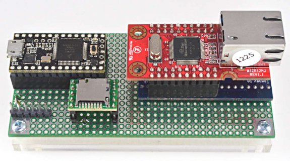
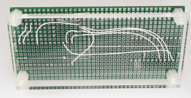
This definitely does work when connected properly. I can't tell what's wrong from this description, but maybe these photos of a known-good connection might help?

t3_wiz812_1.jpg

t3_wiz812_2.jpg
(click for full size image)
 
I should mention only 6 wires need to connect between Teensy3 and the Wiz812 adaptor. In this photo, you should see 5. Ground is connected through the ground plane on the top side of the vector board.
 
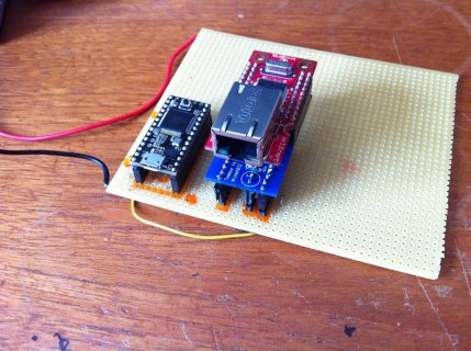
IMG_1466[1].jpg

Heres a picture of my wiring, it looks right to me, I've checked for shorts and that pins correspond...
 
Yes there all in the teensy position not the ++
I've continuity checked from the pins on the wiznet board to the teensy too, they're all routed correctly.
I've tried to order another wiznet board but theyre out of stock, so will keep looking in case its a duff board.
Any other suggestions I can try?
 
I can sell you one of my WIZ821MJ for $10 as it's collecting dust. I've moved to the WIZ820io
Paul is correct (of course!) the WIZ812MJ should work out of the box as it employs the W5100 Ethernet controller that is the same as on the Arduino Ethernet shield. I've not used it with a Teensy3 though, only with a Teensy++2.
 
The WIZ812MJ runs at 3.3V. If you supply 5V through USB ging to the WIZ812MJ you need a voltage regulator that drops it down to 3.3V like the MCP1825 S33 that Paul uses on his WIZ812MJ adapter board.

If you are using the 3.3V from the teensy3 then that may not be enough juice for the WIZ812MJ as the on-board voltage regulator on the Teensy3 only can supply 100mA.
 
Hi Headroom
Thanks for the offer, but I'm in the UK, so it would take a while to get, and I have a clock ticking :)
I managed to find one here, should get it on monday, so I can then rule it out if its not that problem!
The board is being run from a 5V supply not usb, so the current should be fine, the board could be fried, as I was using a DIY 3.3v regulator when initially testing this board but it wasn't working off that either, but then no lights came on that time, now I have lights on the wiz board, but just can't ping it, or connect etc
I'm hoping the board is fried really as I would then know why it doesnt work (albeit a bit down in pocket!), if it isn't, its more perplexing!
 
Aha. yes you being int the UK would make that infeasible on a tight timeline.

For my own experiments I've backed the Hydra Project on Kickstarter. I am hoping to have on in hands soon.
In the meantime I've used these very nifty little Switched DC/DC converters from Traco Power.
Breadboard spacing an while not cheap (~$14 here in the US) these are very handy for little micro controller projects.

Again, you may have blinking lights on the WIZ812MJ but 5V not only is too much for it, I am not sure when you supply 5V to the WIZ812MJ at what voltage level the outputs on it interface with the Teensy3. The IO on the Teensy3 are also not 5V tolerant!

EDIT:
Scratch that. I see that you are using the WIZ812MJ adapter, which has the 3.3 V regulator on board so in theory electrically everthing, should be OK. In that case, perhaps you want to post some code. As time permits this weekend I'll try to replicate your situation here on a breadboard as I have both a Teensy3 and a WIZ812MJ with the Adapter board.

What are you trying to achieve with your project ?
 
Last edited:
Currently I'm just trying to get the board working, so loading the examples from the arduino library, so it should just work, I've tried several examples, and tried deleting the serial write, etc.
Can't ping it, and get the server IP of 0, I can only think its hardware really!
 
This may be a dumb question, but have you checked to make sure none of the signal lines are shorted to each other, or to ground or Vcc?

If using a beeper test, do it with both devices removed. Some of those multimeters (like a Fluke one I have) put a lot of current through the leads in continuity/beeper mode.
 
The 812MJ uses a lot of current... like 150mA or more, due to the rather old 8051 core.

When using the SPI interface, don't ground the CS pin; that was ambiguous in the user docs.

On the reset pin, I suggest a 2K pull-up ad an RF-competent bypass cap - I had trouble with noise and RF (nearby 802.15.4 radio) getting on the reset line. I'd connect RESET to a GPIO line so your program can reset the 812MJ. There is a software command to reset, but once in a great while, the 812MJ gets stuck and needs a hard reset or power-cycle; very rare, but if it's in an unattended situation, your program can reset.
 
Last edited:
Ok so still not having any joy.
Serial monitor now gives 255.0.0.0 or this time 0.255.255.0 as its ip, and I can't ping.
On the wiznet board, some pins messure 5v others 3.3 or 2 others 4v, is this right? Should theyt not have a max of 3.3v?
I've tried 2 adapter boards, both give the same results, got a second wiznet now but don't want to add that just yet in case of power issues.
I have just checked the legs of the regulator, when I built it, one leg gave 3v, now both give 5v, so I presume thats fucked (and both boards now do this), is this what happens to regulators when they go?
Whats the max psu I should be using with this? I've got a fairly beefy one, as I plan to run LED's off it too, is the regulator trying to regulat the full current and frying? How do I power it if this is the case?
I have the voltage going in throught the +/- pins on the adapter BTW is this correct?
There are no shorts, I've checked every pin.
I have no reset connected, is this an issue?
Pulling my hair out here!
 
code is straight webserver example in the arduino library.
Bottom of the board is further up the thread.

I think my issue is probably that the voltage regulator isn't working, ie the board is getting 5v not 3.3v, how do I limit the current going through the regulator?

phototop2.jpg
 
812MJ takes 3.3V at about 185mA. This needs to come from a regulator that would be independent of the Teensy3.
The current through the regulator is that which the 812MJ demands. The 812MJ's 5100 chip usually runs quite warm to the touch.
The input to that regulator needs to be 5V or less else the regulator would overheat. The regulator needs a good heat sink. Is there a regulator on the adapter board?
 
While it is not visible in the image the board is the official WIZ812mj adapter board available through PJRC. That does include an MCP1825 s33 voltage
Regulator and there is plenty of cooling copper on both sides and thermal vias on the board to keep the MCP1825 cool. I've got two of these myself that I used with Teensy++2 and that worked out of the box with the WIZ812mj
 
Is there a regulator on the adapter board?
Yes.
I've now used a new teensy powered via usb, a different psu that puts out 3 volts at a lower current, (300ma)that goes into the adapter board for the wiz.
The pins on wiz now read 3v and below, not 5 which is good (its a new wiz board too)
Siganls are still as they were in the pictures, and I still get server 0,0,0,0

I've checked the signal cables run from the correct pin on the wiz to the correct pin on the teensy3 as in the etherent doucment
I have flashing lights on the wiz board.
I have an led on on the teensy3
Still doesnt work, I have no idea what to try next.
I'm at a complete loss!
 
I am suggesting that this is a software and/or network comfiguration problem. If your router is set up to issueIP addresses per DHCP, which is likely, then have the Arduino request one per DHCP.
So it's not
Ethernet.begin(mac, ip);

But only :
Ethernet.begin(mac);

Look for the code example from user zoomcat on the Arduino forum. I've used that successfully many times.
 
If you had 5V on the 812MJ's pins, I worry about damage. Perhaps not.
On the 812MJ - J2 pin 1 is 3.3V, with respect to ground on J2-20?
Filter capacitor on output of regulator (have schematic of adapter board?)
Common ground to Teensy?

used ohm meter or continuity beeper (w/power off) for all wiring?
 
The board was designed and is sold by PJRC and as such does have a Filter capacitor. I have used it twice in projects without problems. There is no schematic
online but the assembly instructions are clear.
 
I think my issue is probably that the voltage regulator isn't working, ie the board is getting 5v not 3.3v, how do I limit the current going through the regulator?

If the 812 has been driving with 5V power, it's probably damaged.
 
if wiring is OK, you can test by writing a R/W register with a bit pattern and read-back. Such as the MAC address register(s)
 
Status
Not open for further replies.
Back
Top