Op amp help

Status
Not open for further replies.

turtle9er

Well-known member
Hi,

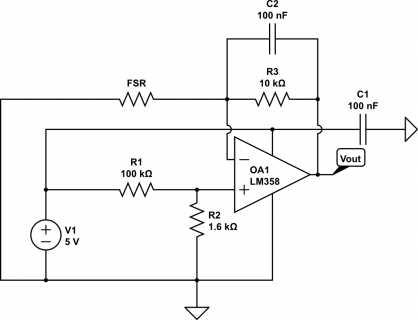
I am working on a project where I need to measure heel strike while walking. A cheap and simple way is to use an FSR, however I am having issues with getting a clean signal. Below is an image of my circuit diagram that is giving me a linear output (resistance of FSR does not change in a linear function), however one issue is the noise, which was greatly reduced using a 100nf cap between the negative input and output. The other issue is that the voltage offset is around 80mv, where I would like it to be closer to zero. I am using the lm358, just because it is what I had, plus I don't know enough about what op amp I need. I am just looking for some feedback on if my circuit is actually correct and if there is better op amp out there that will suit my needs. Thanks.
fsr_linear_buffer.png
 
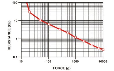
First, some info about the FSR is needed. You didn't post any details. Here's a graph from Adafruit:

resistanceforce.jpg

Assuming your sensor is similar, I can't see how this amplifier circuit could work reliably. When the sensor is not compressed with any force, it's essentially an open circuit. So the amplifier is just sitting there with the negative input connected only to the output (via a resistor and capacitor), but nothing controlling the input. Well, nothing but the leakage current from the LM358's PNP input transistor.
 
Your offset voltage is 80 mv because of the voltage divider you put on the positive input of the opamp, that is formed by the 100k and 1.6k resistors; you can simply remove those and connect the positive input to ground.That should also eliminate most of the noise, since that could be caused by the 5 v output of the teensy, which is actually the 5 v from the USB connector, which is very noisy. To further reduce noise, place the 100 nF cap between the positive power input of the opamp and ground as close as possible to the chip; if that's not enough, place a 1 or 10 uF electrolytic cap in parallel with the 100 nF I said before, this time it doesn't have to be as close as possible. You can easily remove the 100 nF feedback cap.

EDIT: Paul answered while I was writing, and its post made me notice that you should attach 5 V to the end of the FSR that you put to ground, so that you have a normal inverting configuration; you should also add a series resistor after the fsr to limit the total gain of the circuit, I'd stick it to 10 K so that when the fsr resistance is close to 0 you have a nominal gain of 1 ==> you will see 5 volt at max pressure; you can see more details of this configuration on Wikipedia, to understand better why there should be a gain limiting resistor.
 
Last edited:
The trouble with this circuit is the amplifier basically operates open loop when the FSR becomes very high impedance. I can't see how that will ever work well, no matter how many capacitors are added in various ways. Opamps have an incredible amount of voltage gain, so if you let it run open loop with no signal input, it's just sitting there with no input (other than noise) and maximum gain.

A better design is needed. Even just a simple voltage dividor with the FSR and a fixed resistor would work better, but of course it does nothing for the non-linear response.
 
I'd suggest a "EasyDrive" ADC from LTC for this application (i.e. LTC2485 or LTC2484). They are specifically made to handle very high impedances. With the right ADC (24 bit) and board layout, you should be able to handle the very wide range of impedances shown in the adafruit graph.
 
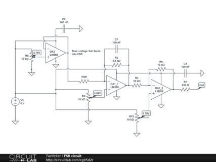
Thanks for all that feedback. I am using Interlink 402 FSRs, however I have found two different pdfs that show slightly different resistance outputs, however both follow a similar non linear pattern. I also attached another circuit diagram that I reverse engineered from an older piece of equipment that was used in our lab. For my final product I need 8 fsrs all attached at once, so from the new diagram you can see that each FSR uses 1 two circuit op amp and also 2 trim pots to regulate the voltage. I am wondering if I could just feed that set voltage into each op amp, instead of using a voltage divider to create that voltage for each FSR. In the end I hope to make a circuit board where it could be worn on person....so keeping the number of parts down would help keeping it as small as possible. Thanks again for the help.

540x405.png
 
^^ Thanks for that pdf, however there seems to be no circuit that gives a linear output. The other issue is that I need the sensors to measure higher force since ppl are wearing these in their shoes to detect heel strike or toe off. I am confused since the pdf says up to 1kg, but with my first circuit I can get up to 3.5V pushing as hard as I can on it, which I hope is greater than 1kg.
 
Why do you need completely linear output? Some of those circuits come more than close enough in my book, that you can just add a bit of digital post-processing.

I doubt your accuracy will be all that great in the first place, since you more than likely won't have very even pressure distribution.
 
I guess a true linear is not needed, really all I need is a way to measure peak force. I guess my main issue is creating an output that won't top out at a low force. I will try some of those circuits from the interlink pdf and see what results I get.
 
Yup. Your best bet, IMO, is to figure out the range of the digital output codes, then create a map of the codes vs. measured impacts. If it all comes together as I expect it will, a logarithmic interpolation will get you there with maybe 30 data points and excellent correlation.
 
I would start by just connecting it from VCC to the analog pin, and a fixed resistor from the pin to ground. Perhaps start with 1K.

With no force, you'll see zero volts, because the FSR is a high impedance and the 1K resistor will keep the pin at ground. When force is applied, the voltage will increase. Unfortunately, because of the non-linear response, it'll be only a very tiny voltage until there's pretty substantial force. But if you're only looking for peaks, maybe you can find a fixed resistor that puts all the peaks you need into a usable range for the Teensy's analog inputs?

No matter what you do, the voltage can only approach VCC, because at maximum force the FSR can act like a low value resistor, so together with the fixed resistor this extremely simple approach will always give you a voltage in the range of the analog input. You just need to find a fixed resistor value that's not too high (where you're sensitive to small forces, but almost everything results in measuring the maximum signal) and not too low (where only a huge amount of force creates any substantial signal).

If you're only looking for peaks, a simpler circuit with only 1 well-chosen fixed resistor, and some math done on the measured voltage is probably the best approach. Of course, you'll need to keep reading the signal rapidly to look for the peak, discarding all the non-peak data.

If you were looking for measurements of different forces and needed them to be highly accurate over a wide range, then a log amp would probably be needed. But building logarithmic circuits is tricky business. Not of those circuit above do this. It usually involves the voltage-to-current relationship of a transistors base-emitter junction. But it's really tough, because that changes pretty substantially with temperature. It's also useful over a pretty small voltage range, only part of the 0.7 volts we normally think of for a P-N junction voltage. There are ways to deal with these issues, but they're not easy or simple.

I'd start with the simplest way, not using any opamps at all, and then make it more complex only as necessary.
 
Also, looking at that 3 opamp circuit, I still don't see quite how it can work.

Maybe it's meant to work as a simple amplifier, or maybe the 2nd opamps is intended to work as an integrator. My guess is it's meant for the FSR to be subjected to a pulse, causing it to temporarily become a lower impedance. During that time, current flows through it, since one side has 3.78V from the 1st opamp and the other side has 2.56V due to the feedback of the 2nd opamp. If C1 is large and R2 is a relatively high impedance, that would cause C1 to charge up to a voltage corresponding to the integral of the force, and R2 would slowly discharge it (presumably well after a microcontroller has read the voltage).

But if R2 is a low impedance and C1 is small, then the middle opamp works more or less like a normal signal amplifier, with a slightly slowed response. Capacitors in feedback loops are often needed when the input pin might have significant capacitance (maybe if the FSR isn't located close to the opamp), because the delay from the feedback resistor and input capacitance causes signal phase shift that can make the opamp unstable.

If I were designing an integrator-based approach, I'd probably put a couple 74hc4066 analog switches in to reset the integrator.
 
Well went back to the basics and did a simple voltage divider setup like Paul said, and it works well, however the voltage jumps up pretty quick due to the nature of the FSR. I found this site http://apollo.upc.es/humanoide/trac/wiki/PressureSensors that talks about the current to voltage setup similar to what is shown in the Interlink integration guide. I don't have a zener diode to test this set up, only have a schottky, which I assume can't be used. In the guide it says to place the diode in parallel with Rg, but I am not sure if that website did the same, they put the diode onto the non-inverting input....also, it seems this set up will go from Vcc at no force, to 0V at max force. From the integration guide it seems this gives a bit more of a linear output. Sorry for all the questions, have no electrical training, so learning as I go. Thanks again for all the great information.
 
By "measuring heel strike", do you mean you want to measure the force that is imposed on the heel when it hits the ground, or just to measure when a heel strike did occur? In the latter case you could even use a digital input in conjunction with the simple resistive voltage divider paul mentioned. the value of the fixed resistor would define the force at witch the pin would "trigger", e.g. have a low-high-transition. step/heel-strike counting could then easily be made interrupt driven.
 
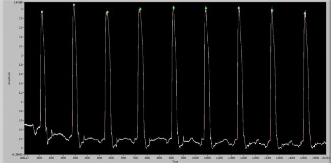
^^ It is just being used to indicate heel strike and toe off, so there will be 2-4 FSR in a shoe at once. The FSR can't really be used to define a force without some sort of calibration done prior to each experiment. To determine heel strike it is easier to do this all post process since every person is different and will produce different voltage thresholds, plus it is common to use the value half way to peak as actual heel strike. If we are withing a few sample that is fine, this data is just used to split muscle activity per step. Thanks again for all the help. The simple voltage divider is working pretty well, attached is running at 8mph, white is raw signal, red is filtered (hard to see under the white) and the green dots are absolute peak value. VD_1k_8mph.jpg
 
Status
Not open for further replies.
Back
Top