You are using an out of date browser. It may not display this or other websites correctly.
You should upgrade or use an alternative browser.
You should upgrade or use an alternative browser.
Encoder library missing pulses
- Thread starter Will
- Start date
- Status
- Not open for further replies.
PaulStoffregen
Well-known member
That encoder arrived last week. I haven't hooked it up yet.
Before I do, perhaps it might be worthwhile to talk about what "real world" really means, in terms of testing?
Before I do, perhaps it might be worthwhile to talk about what "real world" really means, in terms of testing?
PaulStoffregen
Well-known member
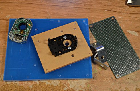
First step - center punched and ready to drill.
They sure don't allow much tolerance for the hole positioning on that encoder mounting bracket using 4-40 screws. I'm going to thread the holes for the screws mounting the encoder, but oversize the 2 holes holding the stepper motor to allow a little tolerance in my drilling and still (hopefully) keep these shafts aligned well.

They sure don't allow much tolerance for the hole positioning on that encoder mounting bracket using 4-40 screws. I'm going to thread the holes for the screws mounting the encoder, but oversize the 2 holes holding the stepper motor to allow a little tolerance in my drilling and still (hopefully) keep these shafts aligned well.

PaulStoffregen
Well-known member
PaulStoffregen
Well-known member
Fully built.....
TL;DR = The Encoder library is working perfectly with 1024 pulses/rev.
I'll probably shoot a quick video later today to demonstrate. It's really pretty amazing how well it works, with exactly 4096 counts on each rev. It's exact, even after 100 turns. You can even see the tiny effect of the stepper overshoot (even with AccelStepper slowing the steps) and settling back to the exact correct position.
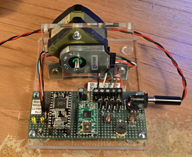
(click for larger image)
Here's the code I'm running on the Teensy 2.0 controlling the motor:
The circuitry is just four 2N2222 transistors and 1N5817 diodes connected to the 4 unipolar phase lines, and the common line to the positive power. The thumbwheel connects to analog input A0, and the 2 pushbuttons connect to port pins read with the Bounce library. The first button causes exactly 360 degrees rotation. The other button causes 10 full turns. The pot sets the speed.
On the Teensy 3.0, I'm running Encoder's "Basic" example.
TL;DR = The Encoder library is working perfectly with 1024 pulses/rev.
I'll probably shoot a quick video later today to demonstrate. It's really pretty amazing how well it works, with exactly 4096 counts on each rev. It's exact, even after 100 turns. You can even see the tiny effect of the stepper overshoot (even with AccelStepper slowing the steps) and settling back to the exact correct position.

(click for larger image)
Here's the code I'm running on the Teensy 2.0 controlling the motor:
Code:
#include <AccelStepper.h>
#include <Bounce.h>

AccelStepper motor(4, 7, 8, 9, 10);
Bounce button1(4, 10);
Bounce button2(5, 10);

void setup() {
  pinMode(4, INPUT_PULLUP);
  pinMode(5, INPUT_PULLUP);
  delay(10);
  motor.setMaxSpeed(400);
  motor.setAcceleration(1500);
}

unsigned long target=0;

void loop() {
  motor.run();
  button1.update();
  if (button1.fallingEdge()) {
    target += 100;
    motor.moveTo(target);
  }
  motor.run();
  button2.update();
  if (button2.fallingEdge()) {
    target += 1000;
    motor.moveTo(target);
  }
  motor.run();
  if (motor.distanceToGo() == 0) {
    int in = analogRead(A0);
    motor.setMaxSpeed(map(in, 0, 1023, 10, 400));
  }
}
The circuitry is just four 2N2222 transistors and 1N5817 diodes connected to the 4 unipolar phase lines, and the common line to the positive power. The thumbwheel connects to analog input A0, and the 2 pushbuttons connect to port pins read with the Bounce library. The first button causes exactly 360 degrees rotation. The other button causes 10 full turns. The pot sets the speed.
On the Teensy 3.0, I'm running Encoder's "Basic" example.
Code:
/* Encoder Library - Basic Example
 * http://www.pjrc.com/teensy/td_libs_Encoder.html
 *
 * This example code is in the public domain.
 */

#include <Encoder.h>

// Change these two numbers to the pins connected to your encoder.
//   Best Performance: both pins have interrupt capability
//   Good Performance: only the first pin has interrupt capability
//   Low Performance:  neither pin has interrupt capability
Encoder myEnc(5, 6);
//   avoid using pins with LEDs attached

void setup() {
  Serial.begin(9600);
  Serial.println("Basic Encoder Test:");
}

long oldPosition  = -999;

void loop() {
  long newPosition = myEnc.read();
  if (newPosition != oldPosition) {
    oldPosition = newPosition;
    Serial.println(newPosition);
  }
}
PaulStoffregen
Well-known member
Here is a video demo.
Can you provide more information (a schematic or diagram) on the four 2N2222 transistors and 1N5817 diodes. I have tried controlling the voltage with resistors from 10ohm to 100kohm with no success. I can get close with 619ohm resistance on both channels but still get slight undercount after 200-300 turns.
PaulStoffregen
Well-known member
Sure. The 2N2222 part I used came from Digikey. The full part number is P2N2222AGOS-ND (they were purchased years ago, but still in a bag with that part number on it). All 4 transistors have their emitter connected to ground. Each base connects to a 470 ohm resistor, which then connects to an I/O pin. Each collector connects to one of the 4 phase lines from the motor. The common line connects to +12 volts.
The 1N5817 diodes are ones I've had in my parts drawers for many years, so I don't know the exact part number from Digikey. One possible part number would be 1N5817-BDI-ND. Each diode is connected with the anode to the motor line (and transistor's collector) and the cathode to +12V.
Here's page about the Stepper library, which has a nice photo of the same circuit built on a breadboard.
http://www.pjrc.com/teensy/td_libs_Stepper.html
This particular circuit uses 2N3904 transistors and 1N4937 diodes. Almost any NPN transistors able to handle the motor's current will work. Almost any "fast" or schottky diode will work. When you connect the transistors, pay close attention to the pinout from the datasheet. The 2N3904 and 2N2222 are not the same pin order.
You can also use stepper motor driver boards, like the 3 I used when I tested the AccelStepper library on this page:
http://www.pjrc.com/teensy/td_libs_AccelStepper.html
Those little Pololu A4988 drivers work great and perform better than just a transistor, since they're meant to use a much higher voltage and they regulate the current. Higher voltage lets the motor spin faster. But they cost more than just 4 cheap transitors and diodes. Be careful when you connect those little modules.... wiring them up wrong with 24 or 30 volts can instantly destroy them.
PaulStoffregen
Well-known member
The 2N2222, 1N5817 and 470 ohm resistors are used to connect the stepper motor to the Teensy2.
For the encoder, VCC connects to VIN, ground connects to GND, "A" connects through a 4.7K resistor to pin 5 and "B" connects through a 4.7K resistor to pin 6.
Actually, I wired A's resistor to pins 3 and 5, and B's resistor to pins 4 and 6, in anticipation of someday testing on those other 2 pins. But for this test, 3 and 4 were unused.
If this description isn't enough, I could take a couple close-up photos. I'm afraid that's about all I can do. I've already spent quite a lot of time on this. I have several other urgent tasks demanding my attention, so I just can't keep pouring more time into this.
PaulStoffregen
Well-known member
470 ohm resistors are used (together with transistors and diodes) to connect the stepper motor to the Teensy2.
For the encoder, "A" connects through a 4.7K resistor to pin 5 and "B" connects through a 4.7K resistor to pin 6, on Teensy3.
For the encoder, "A" connects through a 4.7K resistor to pin 5 and "B" connects through a 4.7K resistor to pin 6, on Teensy3.
PaulStoffregen
Well-known member
Here are close up photos. As usual, click for the full size.
Here's the encoder circuit.
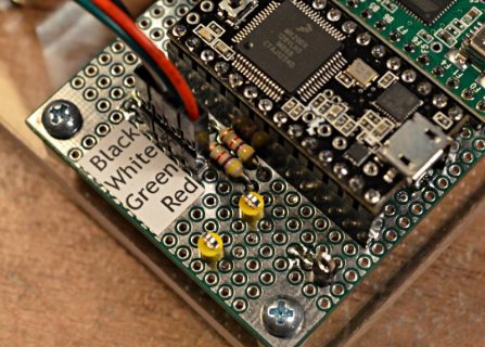
The ground connections are made by soldering a wire nearby to the ground plane on the top of the board.
The A and B signals connect to those 2 resistors, which are 4.7K.
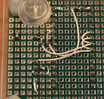
The resistors connect to pins 3+5 and 4+6.
The power is connected to VIN (5 volts from the USB). That little green part is a 100 mA PTC fuse. I also soldered a 4.7 uF capacitor from the power pin to ground. I'm pretty sure the encoder will work without the capacitor, and the fuse is just an extra precaution I took.
Here's the stepper motor connections. The motor connects only to the Teensy2 board. It's totally separate from the Teensy3 reading the encoder.
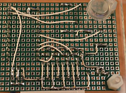
In this bottom side photo, you can see the four 470 ohm resistors. They're soldered at each transistor's base pin, and the other side connects to an I/O on Teensy2. The 4 emitters connect to a wire that goes to ground, and the 4 collectors connect to the large diode wires, which bend over and go right to the terminal block. You can see I bent the cathode side of each diode to go between the terminal block pins, where they all connect to +12V.
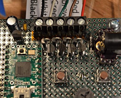
There's actually 1 more diode between the input power and everything the motor and diodes. That's to protect against accidental reverse polarity.
The other part that looks like a transistor is a LP2950 voltage regulator. It creates 5 volts for the Teensy2, so the motor stuff can work only from the 12V power, without USB connected.
Here's the encoder circuit.

The ground connections are made by soldering a wire nearby to the ground plane on the top of the board.
The A and B signals connect to those 2 resistors, which are 4.7K.

The resistors connect to pins 3+5 and 4+6.
The power is connected to VIN (5 volts from the USB). That little green part is a 100 mA PTC fuse. I also soldered a 4.7 uF capacitor from the power pin to ground. I'm pretty sure the encoder will work without the capacitor, and the fuse is just an extra precaution I took.
Here's the stepper motor connections. The motor connects only to the Teensy2 board. It's totally separate from the Teensy3 reading the encoder.

In this bottom side photo, you can see the four 470 ohm resistors. They're soldered at each transistor's base pin, and the other side connects to an I/O on Teensy2. The 4 emitters connect to a wire that goes to ground, and the 4 collectors connect to the large diode wires, which bend over and go right to the terminal block. You can see I bent the cathode side of each diode to go between the terminal block pins, where they all connect to +12V.

There's actually 1 more diode between the input power and everything the motor and diodes. That's to protect against accidental reverse polarity.
The other part that looks like a transistor is a LP2950 voltage regulator. It creates 5 volts for the Teensy2, so the motor stuff can work only from the 12V power, without USB connected.
Interesting (and entertaining) thread...
I came here because I'm also looking for a solution for a general-purpose PID DC servo motor controller. I'm going to start another thread about that... but I just wanted to point out, Will, in case you didn't know, the chip on the Teensy 3 has a dedicated quadrature decoder, capable of counting pulse rates into the MHz, with no impact on the CPU - unlike the encoder library that can eat most or all of the CPU servicing the interrupts for a modest DC servo. It also has built-in filters which are important for motor applications - see the discussion of motor jitter on page 811 of the MK20DX128 manual.
As someone mentioned in another recent thread, it would be great if this was accessible with the encoder library...
Another approach to cut down on the CPU usage is to use some discrete logic, eg. flip-flops or an LS7183 to convert the quadrature signal into up/down pulse trains, and use two timer inputs to count them, and subtract them to find the change in position each time through your servo loop.
Oh and by the way, Paul is 100% correct in saying that an A/B quadrature signal is Gray code, aka "reflected binary": 00 01 11 10 00
However... generally people in the industry only talk about Gray code when they mean absolute encoders, that put out eg. 9-bit or 12-bit Gray code based on a code wheel, giving the absolute position of the wheel at any moment. With incremental encoders, where you have to count the pulses, the term is always "quadrature" (unless it's eg. up/down pulses), even though mathematically speaking it's also Gray code. So everyone is right, depending how you look at it...
Just because it has a quadrature decoder chip doesn't mean it will properly count encoder pulses directly. You would still have to have a second IC between the encoder and the Teensy.the chip on the Teensy 3 has a dedicated quadrature decoder, capable of counting pulse rates into the MHz, with no impact on the CPU - unlike the encoder library that can eat most or all of the CPU servicing the interrupts for a modest DC servo.
If you're going to do that, you might as well use a LS7166 or LS7366 which would do everything for you and store the count in a register.Another approach to cut down on the CPU usage is to use some discrete logic, eg. flip-flops or an LS7183 to convert the quadrature signal into up/down pulse trains, and use two timer inputs to count them, and subtract them to find the change in position each time through your servo loop.
I'm not going to debate technical details any further. Obviously, the hobby market holds a different view of things from the industrial market.Oh and by the way, Paul is 100% correct in saying that an A/B quadrature signal is Gray code, aka "reflected binary": 00 01 11 10 00However... generally people in the industry only talk about Gray code when they mean absolute encoders, that put out eg. 9-bit or 12-bit Gray code based on a code wheel, giving the absolute position of the wheel at any moment. With incremental encoders, where you have to count the pulses, the term is always "quadrature" (unless it's eg. up/down pulses), even though mathematically speaking it's also Gray code. So everyone is right, depending how you look at it...
Jeff, since you asked, I think you'll find that the counting part is quite easy compared to the interface part. The problem I had with Teensy 3 was that I could never get the pulse current from the encoders right. The closest I have come so far is with a 619ohm resistor on both channels. Even that is subject to source voltage changes. Paul said he used 4.7k ohm resistors in his demo video. But, even if you jump through that hoop, you'll find that it's not as easy controlling position of a brushed motor as you might think. If you're using a servo motor, you should already have what you need built into the motor drive circuitry.
Anyhow, in the interest of saving myself a lot of grief, I posed the question on all the major microcontroller forums: "Has anyone been able to successfully control the position a brushed DC motor using a motor controller and quadrature encoder with a microcontroller?"
There were two camps: The first was comprised solely of armchair programmers who have never actually done it but are quite sure it would be no problem. And they have the pseudocode to prove it. The second camp consisted of those who had actually tried it, most of whom were unable to successfully do it. Only one person from Bangkok said he had actually done it with a PIC 40mHz controller in assembly language and even then, he had used external quadrature counter ICs. Here is his observation on his successful attempt to do this, verbatim: "It's a massive project to get all this stuff to work correctly, this project took MONTHS to finish, a gnarly beast."
So, I'll leave it to you to decide which camp knows what they're talking about. Good luck. If you get it working, please let us know.
Last edited:
Just because it has a quadrature decoder chip doesn't mean it will properly count encoder pulses directly. You would still have to have a second IC between the encoder and the Teensy.
If you need a 5V to 3.3V level conversion, there are many ways to deal with that very common requirement, not all of them needing an IC. Also if the encoder is too far away from the chip, you'll need line drivers - for example the CUI-10XE-10 includes that. I mean come on, this is very basic stuff that everyone has to deal with, what is the big complaint?
...even if you jump through that hoop, you'll find that it's not as easy controlling position of a brushed motor as you might think.
I never said that would be easy!
Anyhow, in the interest of saving myself a lot of grief, I posed the question on all the major microcontroller forums: "Has anyone been able to successfully control the position a brushed DC motor using a motor controller and quadrature encoder with a microcontroller?"
There were two camps: The first was comprised solely of armchair programmers who have never actually done it but are quite sure it would be no problem. And they have the pseudocode to prove it. The second camp consisted of those who had actually tried it, most of whom were unable to successfully do it. Only one person from Bangkok said he had actually done it with a PIC 40mHz controller in assembly language and even then, he had used external quadrature counter ICs. Here is his observation on his successful attempt to do this, verbatim: "It's a massive project to get all this stuff to work correctly, this project took MONTHS to finish, a gnarly beast."
So, I'll leave it to you to decide which camp knows what they're talking about. Good luck. If you get it working, please let us know.
Well, there's this, C source code included:
http://ww1.microchip.com/downloads/en/AppNotes/00696a.pdf
Last edited:
After you've tried it, come back and let me know how it worked for you. Otherwise, I'm not interested in your opinion how easy it is.If you need a 5V to 3.3V level conversion, there are many ways to deal with that very common requirement, not all of them needing an IC. Also if the encoder is too far away from the chip, you'll need line drivers - for example the CUI-10XE-10 includes that. I mean come on, this is very basic stuff that everyone has to deal with, what is the big complaint?
PaulStoffregen
Well-known member
The problem I had with Teensy 3 was that I could never get the pulse current from the encoders right. The closest I have come so far is with a 619ohm resistor on both channels. Even that is subject to source voltage changes. Paul said he used 4.7k ohm resistors in his demo video.
Compared to using some off-the-shelf motion controller, which probably comes with encoders that have cables which simply plug in, connecting wires and resistors might seem like a lot of work.
Teensy is about DIY electronic projects.
you'll find that it's not as easy controlling position of a brushed motor as you might think. If you're using a servo motor, you should already have what you need built into the motor drive circuitry.
Throughout this thread, I have tried to stay focused on your original concern, which is strongly reflected in this thread's subject, that the Encoder library misses pulses or otherwise does not work properly under some circumstances (a.k.a. "in the real world"). I believe the Encoder library is working properly.
Closed loop motion control is an entirely different subject. It is not simple. It's also far beyond the scope of the Encoder library, which only gives you the quadrature decoding.
Normally I don't mind when threads diverge into other topics, but because this thread began with such a forceful assertion that the Encoder library was defective, and because I have personally put a considerable effort into retesting the Encoder library, I am asking you you keep this thread on-topic. Specifically, is the Encoder library properly implementing quadrature decoding for these hi-res encoders?
If you'd like to talk about using encoders for motion control, or motion control algorithms, please start a new thread. If this one keeps going off-topic from whether or not the Encoder library works properly, I'll close this thread.
Sorry Paul, didn't mean to barge in on the thread... I started a new one here:
http://forum.pjrc.com/threads/24297-DC-Servo-Controller?p=35907#post35907
I have to say I'm impressed, you really went the extra mile on this one... talk about great tech support!
I guess I was mainly wondering whether in some circumstances, encoder jitter (as described on pg 811 of the MK20DX128 manual) might affect the accuracy of the encoder library count, even if the code is working as intended - as I think you've clearly demonstrated. In other implementations of quadrature decoders, I've usually seen some kind of input filtering (eg. the digital filter on pg 750, or the RC filter used in the Microchip app note). It wasn't entirely clear to me whether this jitter would just be reflected as a fluctuation in the count, or whether it would actually cause a mis-count, i.e., to lose the actual position.
I do have a "real world" project that I have a deadline to get working in the next couple of weeks. I have a Teensy 2, which I had planned to connect to an encoder on a motor, running at up to 3000 rpm. The motor will be postioned by an off-the-shelf controller (since I haven't been able to find an open source one), but I need to get the position data into a PC at the same time, and the controller doesn't give access to the data. So the idea was to parallel the encoder outputs to the Teensy, calculate the position with the encoder library, and simply send it out the USB serial. I need to order the motor system soon, but this thread has made me a bit nervous that the whole plan may not work out, if for any reason the encoder library isn't working properly in this situation.
Anyway, again sorry if that's not relevant to the thread.
Last edited:
PaulStoffregen
Well-known member
Whether the Encoder library works is most definitely on-topic.
How to use Encoder's output to control a motor is another topic entirely. It's also far outside the scope of the Encoder library, which only provides quadrature decoding of the encoder signals. It's perfectly fine to start a new thread for that. Motion control is a large and complex topic.
The Encoder library uses interrupts to track each signal change. Each interrupt response takes a certain amount of time to process. It's also possible for other libraries to be using interrupts, which could prevent Encoder's interrupt from responding as quickly. So there's an upper limit to how rapidly changes can be tracked. If the signal has extra transitions, those too need to be tracked for the total quadrature decode to be accurate. If those "jitter" transitions happen too rapidly, they could be missed. The RC filter is a nice way to absolutely guarantee a signal doesn't have the bandwidth for such rapid changes.
On 16 MHz AVR, I went to quite a bit of trouble to measure the maximum speed, or in other words the minimum time that must elapse between signals changes. That worked out to be about 7.9 microseconds. I haven't repeated this measurement on Teensy3 yet. Probably sometime next year I'll work on Encoder again, to add support for the native hardware, and also to optimize the code a bit more and measure these specific timing limitations. Unfortunately, they type of work takes a pretty substantial amount of time. Right now, I'm juggling several much more urgent projects, so as long as the Encoder library is working and not suffering from some fundamental flaw (and based on everything I've tested, I believe it is indeed working), I just can't invest a lot more time into the Encoder library this year.
Will, I just don't understand what point you're trying to make, if any?
- Status
- Not open for further replies.


