Encoder library missing pulses

Status
Not open for further replies.

Will

Active member
Paul,

This is the issue we discussed earlier today. I purchased the Teensy 3 to read encoders. I have tried unsuccessfully to do this with the ATmega 328 16mHz chip and was not able to keep up with the encoder speed even using the PORT registers. I assumed the faster chip on the Teensy 3 would solve the problem. I have tried this same process on the Teensy 3 using hardware interrupts, the encoder library and direct pin reads (well, as direct as I can get using digitalReadFast). I am only attaching the library method (and associated output) to avoid confusing the issue.

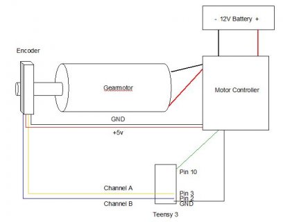
Actually the counts returned by digitalReadFast seem to be closest although they are still short. I have tried this with 6 different encoders across 2 brands: US Digital and CUI. The encoder I am using for the test program (attached) is a CUI MT102-V 2048ppr encoder (http://www.cui.com/product/resource/amt10x.pdf), driven at ~200RPM. The encoder, gearmotor and motor controller I am using for this test have tested successfully in a prior application (using a quadrature decoder) so I know they are capable of doing what I need to do.

I appreciate any light you can shed on this problem.

Will

Attachments: sample program, sample output
 

Attachments

  • encoderTest.ino
    3.1 KB · Views: 316
  • EncoderTestResults.txt
    1.7 KB · Views: 308
I have tried this same process on the Teensy 3 using hardware interrupts, the encoder library and direct pin reads (well, as direct as I can get using digitalReadFast). I am only attaching the library method (and associated output) to avoid confusing the issue.

The code you posted appears to attempt both the Encoder library and direct pin reading.

The encoder I am using for the test program (attached) is a CUI MT102-V 2048ppr encoder (http://www.cui.com/product/resource/amt10x.pdf), driven at ~200RPM.

Wow, that's fast. It may be too fast, even for Teensy3. I'm not sure. I did a maximum speed test on Teensy2 and found 127 kHz was the fastest increment rate (for 4X counting) using interrupts. This is much faster!

I have not tested the max speed on Teensy3. Looks like I should do that soon....

Can you try setting the dip switches for a lower resolution? Even if you need this high res, trying a lower res can at least help shed some light on the problem... if the problem is "only" the inability to keep up with this fast pulse rate, or if the problem is something more fundamental that happens at every speed, even very slow?

From that datasheet, it looks like this encoder runs from 5 volts. Are you powering it from Teensy 3.0's VIN pin?

Are the 2 signals connected directly from the encoder to Teensy pins? If they're 5V signals, series resistors (eg, 1K) or buffer chips should be used to reduce the signal to the 3V signals Teensy3 uses. If you can post a diagram or photo showing how you've actually connected the encoder, it might help.
 
Thanks, Paul, for your response. The only reason for the direct pin reading was to point out the discrepancy in encoder readings. It does nothing otherwise.

The encoder is powered from the motor controller which I have metered at 5.1 volts. I also tried 1k and 2k ohm pullup resistors on the both A and B channels with 2 different encoders. That did not help either.

I have tried this at resolutions all the way down to 256ppr. Doesn't seem to help. If I slow the motor speed down, it doesn't seem to help either. At 200 rpm and 2048 ppr, that's 6820 pps. Based on my calculations, a 24mHz processor should handle that. However, in production, the gearmotor shafts will be turning up to 300 rpm. So, I need to be able to handle up to 10240 pps. Below are the results of 5 tests at 512ppr:

Encoder stopping...
encoder1Pos=512
encoder1ACount=2915
encoder1BCount=2640
M1Distance=512
AMT100.read()=514

SHAFT TURNED 3 REVOLUTIONS

Encoder stopping...
encoder1Pos=512
encoder1ACount=1641
encoder1BCount=1510
M1Distance=512
AMT100.read()=511

SHAFT TURNED 1 1/4 REVOLUTIONS

Encoder stopping...
encoder1Pos=512
encoder1ACount=2188
encoder1BCount=1933
M1Distance=512
AMT100.read()=512

SHAFT TURNED 2 1/4 REVOLUTIONS

Encoder stopping...
encoder1Pos=512
encoder1ACount=1284
encoder1BCount=1228
M1Distance=512
AMT100.read()=514

SHAFT TURNED 3/4 REVOLUTIONS

Encoder stopping...
encoder1Pos=512
encoder1ACount=2038
encoder1BCount=1855
M1Distance=512
AMT100.read()=510

SHAFT TURNED 1 3/4 REVOLUTIONS

Encoder stopping...
encoder1Pos=512
encoder1ACount=1966
encoder1BCount=1793
M1Distance=512
AMT100.read()=511

SHAFT TURNED 2 1/3 REVOLUTIONS
 
If it's not working at slow speeds, then something is more fundamentally wrong.

Can you post a diagram or photo showing how you've actually connected everything?
 
Oh, yes, speed-wise I was thinking per second, not per minute. 300 RPM at 2048 pulses/rev is only 10240 pulses/sec. Even if each pulse is 4 counts, that should be well within the Encoder library's capability.

Why it's not working, I can not say. In a worst case scenario, I could get one of those encoders and test it here. Looks like they're under $24 at Digikey. But first, before I buy this specific encoder, I'd really like to see how you've connected it. This still may be a simple issue.
 
Believe me, it's not simple. The concept is very simple: read a pulse, increment a counter. But it practice, it's not working that way. Attached is a wiring diagram.

As I said, I have tried this with multiple brands of encoders with similar results. I have tried with multiple motors, even different brands. I have tried with two different motor controller brands. The reason I am using the AMT100 and this setup is that I know it works because I can take the exact setup (same wiring, same everything) that I have right now, put a quadrature decoder between the encoder and microcontroller and it works.

I believe you can reproduce this with any encoder, any motor. It is not device specific.
 

Attachments

  • motor_encoder_wiring.JPG
    motor_encoder_wiring.JPG
    33.5 KB · Views: 438
That wiring diagram looks like it should work. There isn't a ground connection directly from the encoder to Teensy3, but if the ground is good between the encoder and controller, then Teensy3 should be getting good signals.

The encoder might be signed 5V signals, but Teensy3 is not 5V tolerant. You should add 1K resistors in series with both encoder signals, located close to the Teensy3.

Regarding decoding the signals, this code is incorrect:

Code:
  byte pinA = digitalReadFast(encoder1PinA);
  byte pinB = digitalReadFast(encoder1PinB);

  if (pinA != priorPinA) {
    encoder1ACount ++;
    priorPinA = pinA;
  }
  if (pinB != priorPinB) {
    encoder1BCount ++;
    priorPinB = pinB;
  }

This is NOT how quadrature encoded signals work! On the encoder page, there's a section called "Understanding Quadrature Encoded Signals", with little wheel you can spin by clicking the buttons. Proper quadrature decoding depends upon inspecting the state of the other signal when each changes.

If the motion is always in 1 direction, and if the signals are good, then this code should agree with proper decoding. But if the motion changes direction, or the signals are not right for any reason, this code will count changes are incrementing in the positive direction when in fact those signal changes may indicate motion in the opposite direction.

Why this system isn't working still remains a mystery to me. But I can say without a doubt that code is incorrect. It's not valid to use that incorrect code as a comparison to the encoder library for the purpose of troubleshooting. Doing that will only add confusion.
 
Last edited:
I understand quite well how quadrature encoders work. As I stated previously, I put the code in there to illustrate to you the erratic readings I am getting from the encoder library. If it bothers you, please remove it.

As I pointed out previously and in the diagram, the encoder is getting a 5V signal from the motor controller, not the teensy. The ground for the teensy is going into the same contact as the ground in the motor controller. They are physically touching.

As I also pointed out previously, I have added 1k pullup resistors to both lines with no visible change.

Have you tested the Teensy in a setting where it reads from an encoder driven by a motor and attempts to stop the motor at a specified position?
 
As I also pointed out previously, I have added 1k pullup resistors to both lines with no visible change.

Not pullup resistors. Resistors in series.

The issue is that encoder probably sends 5 volt signals. Teensy 3.0 is 5V tolerant. Directly driving the I/O pins with 5 volts may damage them.

It's ok to connect a 5V signal with a 1K resistor in series. Every I/O pin has a protection diode between the pin and 3.3 volts. So with a 1K resistor in series, the pin will be driven to about 3.9 volts. About 1.1 volts will be across the resistor, so about 1.1 mA will flow into the pin and contribute to powering the Teensy3 board. As long as the current injected into the pin is less than 10 mA, it's safe. 1K should allow plenty of bandwidth for these signals, and limit the injected current to well under the 10 mA limit.

Connecting 5V signals directly is bad. It might damage Teensy3's pins. Then again, it might work fine, but it stresses the pins more than is recommended.

It's hard to know if this is the cause of all these troubles. My guess is something else is wrong. But you should fix this, so we know it's not an issue.


Have you tested the Teensy in a setting where it reads from an encoder driven by a motor and attempts to stop the motor at a specified position?

No, I have not attempted closed-loop control using the Encoder library. I have tested with several different encoders, but only by observing the number change corresponding to the distance moved. I can only help with getting Encoder to read the quadrature signal. Making closed-loop control is something I have not done.

From the info above, it looks like the Encoder library is always reporting 512, no matter what you do with moving the shaft. Is that what you're seeing?

EDIT: after working with you code, I see you're resetting the count every 512. It still doesn't seem right, because you got 512, first with 3 turns, sometimes with 1 turn, sometimes with 3/4 turn.
 
Last edited:
I just tried running your program on my Encoder library board. It's this exact board, except I plugged a Teesny3 into the socket.

td_libs_Encoder_1.jpg


I had to make a couple small edits to your program. I don't have that motor library, nor the motor, so I commented it out. My board has the encoder on the left side connected to pins 1 and 2, so I edited the pin numbers. These encoders are 24 pulses/rev, and the Encoder library uses 4X counting, so I changed "M1Distance" to 96. The exact code I ran is attached below.

I turned the encoder 3 revolutions. Here is the output:

Ready.
Encoder stopping...
encoder1Pos=96
encoder1ACount=68
encoder1BCount=77
M1Distance=96
AMT100.read()=95
Encoder stopping...
encoder1Pos=96
encoder1ACount=70
encoder1BCount=86
M1Distance=96
AMT100.read()=96
Encoder stopping...
encoder1Pos=96
encoder1ACount=52
encoder1BCount=73
M1Distance=96
AMT100.read()=96

It printed each group of lines as I passed the starting position.

On thing to notice is the two counts show more than 48 changes. This particular encoder I'm using has mechanical chatter. The Encoder library very reliably counts 96 for each revolution. But just looking for changes will triple count some events, because the contact chatter.

I still have no idea why things aren't working well for you.

Maybe you could try this edited code with your encoder set to a low resolution and manually turn it? If you set the dip switches to the lowest res, only 48 pulses per rev, you should be operating at exactly twice the resolution of my test encoder. If you run this exact code and manually turn the shaft, you should see it print 96 every half turn.
 

Attachments

  • sketch_aug27b.ino
    3.1 KB · Views: 211
I believe you can reproduce this with any encoder, any motor. It is not device specific.
Well, I've tested a Teensy 3 with an Avago HEDS-5540 optical encoder (500 counts/rev) and it did work. Wiring was 5V power to encoder; A/B directly connected to Teensy inputs. But the encoder has a very low drive strength (probably >5kOhm output impedance); yours has a much higher drive strength.

Your Teensy isn't getting the right signals maybe because of overdriving the inputs or because of noise. Keep in mind that there is no glitch filtering either hardware or software on the Teensy.
 
Will, if you can run the code I posted just now (no motor stuff) and confirm the problem still exists, and if you'll post a photo of your wiring that doesn't reveal any problems, then I'll order that exact same CUI encoder from Digikey and test it sometime next week.

Other than running your code successfully here, that's pretty much the final thing I can do.
 
BTW, if your motor/encoder isn't close to the Teensy, you might want to consider a RS422 driver at the encoder and a RS422 receiver at the Teensy. If you use twisted pair wiring, you will be immune to pretty much any amount of noise and you automatically have a level shifter by using a 3.3V receiver.

The RS422 stuff is extremely cheap and you can get it in tons of different packages.
 
This might be noise, or incorrect wiring, or some other unknown problem. It also might be a bug in the Encoder library or some problem with this CUI encoder, but I believe those are pretty unlikely.

Definitely the next step in troubleshooting would be to connect this CUI encoder directly to a Teensy3 (just 4 wires and 2 series resistors on the signals, using the VIN pin to power the encoder), without the motor controller or other stuff connected. Testing should be with simple code that just prints the Encoder read() number. Does manually turning it one revolution produce the right count?

That's such a simple thing to test. If I had that specific encoder here, I'd just do it right now.
 
The 1k ohm resistor on both channels solved the signal problem. It sucks that ARM made this chip 3.3v since most commercial products operate at 5+ volts. Are there any plans to bump up the voltage tolerance of the pins? Otherwise, I have to pay someone to put resistors on every single one of these things if I decide to go this route.

I believe there are a couple of problems with the encoder library.

First, the count it returns is 4x the count that it should be. For example, on a 2048 line encoder, if I stop the shaft at 2048, I only get a quarter of a turn. Seems to me the number passed to the encoder routine should be encoder resolution x desired number of revolutions. Anyhow, that's not a dealbreaker. I can always multiply by 4.

The second problem is the encoder routine is not returning an accurate count. The count returned by the routine seems to be always low, therefore causing overruns. I have tested this exhausively in my setup over hundreds of iterations. I have been able to successfully drive the motor to the desired position using both interrupts and pulse counts, using my routines. However, when I call the encoder.read() routine to get the count, the motor overruns the distance every time. I know the pulses are coming back correctly, because as I just pointed out, I can count them with interrupts (or digitalReadFast) and get the precise distance every time. Again, not a dealbreaker. I can use my own routines. But it may be something you want to look into.

I haven't tested this at speeds over 100RPM, as I need to build in error correction for speeds greater than 100RPM because the gearmotor overshoots because of momentum. I will let you know how that turns out. I was previously able to read encoder speeds up to 1280ppr @ 200RPM using a simple Arudino Uno so certainly this chip should handle it.
 
First, the count it returns is 4x the count that it should be. For example, on a 2048 line encoder, if I stop the shaft at 2048, I only get a quarter of a turn. Seems to me the number passed to the encoder routine should be encoder resolution x desired number of revolutions.
The lib gives you the maximum possible accuracy. With a good encoder, you have a 90deg phase between A/B and a 50% duty cycle. That gives you an accurate resolution that is 4x the PPR.

You likely still have spurious signals. You should check that encoder.read() always counts in the same direction, while your motor is turning that direction.
 
tni, I appreciate you effort to help. However, did you read my post? I am getting the correct values with direct reads. The library doesn't give you any more accuracy that what the encoder is capable of. I beleive you are referring to gray code which this encoder does not emit. In any event, I don't need the library. I was merely pointing out these issues so if Paul wants to address them.

What i do need is a board that will tolerate 5+v. If you know of one that is fast enough to count pulses off two quadrature encoders at 10240pps, send and receive messages via SPI while concurrently synchronizing two motors with a PID, I would be happy to hear about it.
 
Last edited:
tni, I appreciate you effort to help. However, did you read my post?
Yes.
I am getting the correct values with direct reads.
Maybe, maybe not. I had the impression that you are only counting pulses on a single channel, so noise on the second channel might be ignored. That noise would make the encoder lib count backwards and result in a count that is too low.
The library doesn't give you any more accuracy that what the encoder is capable of. I beleive you are referring to gray code which this encoder does not emit.
Nope, I'm talking about quadrature encoding, e.g. a random page that shows the A/B pulse trains:
http://granitedevices.com/wiki/Quadrature

So for each pulse, there are 4 edges, 2 rising and 2 falling. Ideally, (90deg phase, 50% duty cycle) they are evenly spaced and give you 4x the resolution you would get if you only counted pulses.
 
I am getting the correct values with direct reads. The library doesn't give you any more accuracy that what the encoder is capable of. I beleive you are referring to gray code which this encoder does not emit. In any event, I don't need the library. I was merely pointing out these issues so if Paul wants to address them.

I do indeed want to address any possible problem with the Encoder library.

However, the Encoder library is designed for quadrature (gray code) signals. Are you sure this particular CUI encoder is not quadrature? Yes, that would explain why Encoder is not giving correct results.

Virtually all encoders are quadrature signals. Maybe this one just isn't? Sounds like I need to just buy one and test it here.....


What i do need is a board that will tolerate 5+v. If you know of one that is fast enough to count pulses off two quadrature encoders at 10240pps.

Teensy 2.0 is probably just barely fast enough, at least using the Encoder library. As you can see on Encoder's web page, the library was tested to use nearly all the CPU time with an interrupt rate of 127 kHz.

Two 10240pps encoders (which are 41960 interrupts per second) would use about 65% of the CPU time, leaving 35% free for your program. Normally SPI communication does not disable interrupts, so it should work.

If you wanted a simple pulse count at that speed, you might be able to adapt the Encoder library code. But it's highly optimized code that's not easy to edit, with the interrupts implemented in assembly.
 
Just because it's quadrature, doesnt mean it outputs gray code. Quadrature refers to the 4 signal changes per cycle. Gray code determines how it emits those signals.

Your spec sheet says the Teensy 2.0 is 16mHz. 16Mhz won't even keep up with one encoder at 10240 pps. I've already tried that which is why I bought the Teensy 3.

I don't believe the AMT102 ouptuts gray code. Digikey says no. I am trying to get a definitive answer from CUI but their main number rings busy 100% of the time. I have sent them an email requesting clarification. However, I am hoping to use the US Digital encoder since it is smaller and I need as small as possible. There is no evidence it outputs gray code either.

If your library only works with gray code encoders that might explain the discrepancy, although I would expect it to be off by more than I am seeing.

Maybe you can tell me a small-footprint high-resolution encoder that outputs gray code at 3.3v that you have tested with? I am not aware that such a thing exists. The votage difference is my biggest problem at this point.

Thanks, Paul.
 
Just because it's quadrature, doesnt mean it outputs gray code. Quadrature refers to the 4 signal changes per cycle. Gray code determines how it emits those signals.
Do you have a reference for a quadrature encoder that doesn't put out 2-bit gray code?
I don't believe the AMT102 ouptuts gray code. Digikey says no.
The spec sheet says 50% duty cycle square wave with 90deg phase difference between A/B - that's 2-bit gray code.
 
Your spec sheet says the Teensy 2.0 is 16mHz. 16Mhz won't even keep up with one encoder at 10240 pps. I've already tried that which is why I bought the Teensy 3.

How did you test this?

As you can see on the web page, I tested with a synthesized quadrature signal. The 16 MHz CPU was able fully utilized around 127000 changes per second. That corresponds to 31750 pulses per second. It should be easily able to handle only 10240 pps.
 
If you want to call 2-bit gray code, gray code, fine. 2-bit gray code is exactly the same as 2-bit binary. There is no difference. As far as I am concerned this is a misnomer invented by salespeople trying to sell something they don't have.

I have tested this with multiple 16mHz arduinos. I cannot get a 16mHz arduino to handle more that 1280 interrupts per second while driving a motor.

Do you know of a documented example where a 16mHz board has actually driven a motor at 300RPM and counted pulses from a quadrature encoder at 2048ppr?
 
Status
Not open for further replies.
Back
Top