Powering neopixels (WS2812 leds) with Teensy 3.0

Status
Not open for further replies.

MichaelMeissner

Senior Member+
I've recently picked 2 Adafruit's neopixel rings (16 leds using WS2812), and I have a few more neopixels on order, and I had a question about powering the leds.

According to Adafruit, the draw is 5 volts and 1 amp for 16 LEDs all at full power, with the leds supporting 4-7v. With my two rings, I used the Teensy's VIN pin to power the LEDs, on the assumption that VIN was before the voltage regulator, and 1-2 amps could go to the leds, and the Teensy would take whatever it needed. However, if VIN has limitations on the amperage, I would need to rework things.

At the moment, I'm not running the teensy where I have all leds turned to white, but I may do this in the future. When I'm not programming it, I've been thinking of running it from a 4 Nimh AA battery pack (4.8v and/or regulated up to 5v) and/or a 2amp USB cell phone battery charger. At this power level, would it be safe to use the VIN pin? Or do I need to have two power units, one for the teensy and one for the LEDs (or one unit, and split the power before it gets to the teensy)? I realize for larger amounts of lights, you need to do multiple power supplies, but I was hoping to only have one power supply in this configuration. If things will work, but the lights are dimmer, I can live with that.

Thanks in advance.:cool::confused:
 
According to Adafruit, the draw is 5 volts and 1 amp for 16 LEDs all at full power

That sounds about right. On full each pixel uses 0.25 Watts / 50 mA so about an amp-ish draw.

With my two rings, I used the Teensy's VIN pin to power the LEDs, on the assumption that VIN was before the voltage regulator, and 1-2 amps could go to the leds, and the Teensy would take whatever it needed. However, if VIN has limitations on the amperage, I would need to rework things.

Are you saying you're using the computer's power over USB to drive the LEDs? I don't think that will work; I think USB is limited to 500 mA @ 5V.

When I'm not programming it, I've been thinking of running it from a 4 Nimh AA battery pack (4.8v and/or regulated up to 5v) and/or a 2amp USB cell phone battery charger. At this power level, would it be safe to use the VIN pin?

If you mean plugging a 2 Amp charger's micro-B connector into the Teensy's USB socket then no, I don't think that will work just from the standpoint of pushing 2 Amps through the copper trace on the Teensy's PCB. This calculator http://circuitcalculator.com/wordpress/?p=25/ says 2 Amps needs a minimum 31 mil trace for that, and the way I see the board it doesn't have that wide of one.

If you mean a different kind of physical connection then yes that will work, I'm actually doing something similar for a project I'm working on. I've got a 5V 4A power supply connected to my WS2812 banks and the VIN of my Teensy. I did cut the VIN/VUSB pad per http://forum.pjrc.com/threads/19228-confused-again-Cutting-VIN-from-VUSB-Teensy-3-0, so the power supply needs to be plugged in to program my Teensy, but other than that no issues.

If things will work, but the lights are dimmer, I can live with that.

For what it's worth in my setup I'm limiting the LEDs to ~ 25% maximum (19 levels of PWM using values 0, 1, 2, 3, 4, 5, 7, 9, 12, 15, 18, 22, 27, 32, 38, 44, 51, 58, 67) and even at that level they're pretty bright; definitely bright enough for my needs.

I hope this helps. Good luck!
 
Are you saying you're using the computer's power over USB to drive the LEDs? I don't think that will work; I think USB is limited to 500 mA @ 5V.

At the moment, I'm running patterns which only have some of the lights on, so it should be within the 500 mA from the laptop. However, one of the things I want to do, is use the ring as a focus assist light on the camera, and I would probably want to turn all LEDs on (one ring, so 1a power). I haven't done that yet, so I thought I would ask before rushing in.

If you mean plugging a 2 Amp charger's micro-B connector into the Teensy's USB socket then no, I don't think that will work just from the standpoint of pushing 2 Amps through the copper trace on the Teensy's PCB. This calculator http://circuitcalculator.com/wordpress/?p=25/ says 2 Amps needs a minimum 31 mil trace for that, and the way I see the board it doesn't have that wide of one.

Yep, that's what I was concerned about. I think it may be time to plan on doing it the 'right' way.

If you mean a different kind of physical connection then yes that will work, I'm actually doing something similar for a project I'm working on. I've got a 5V 4A power supply connected to my WS2812 banks and the VIN of my Teensy. I did cut the VIN/VUSB pad per http://forum.pjrc.com/threads/19228-confused-again-Cutting-VIN-from-VUSB-Teensy-3-0, so the power supply needs to be plugged in to program my Teensy, but other than that no issues.

Yep, so far I haven't cut VIN/VUSB.

For what it's worth in my setup I'm limiting the LEDs to ~ 25% maximum (19 levels of PWM using values 0, 1, 2, 3, 4, 5, 7, 9, 12, 15, 18, 22,
27, 32, 38, 44, 51, 58, 67) and even at that level they're pretty bright; definitely bright enough for my needs.

I hope this helps. Good luck!
Yep, those lights are really bright. Thanks for the answer.
 
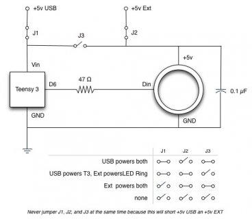
Teensy 3 + LED Ring.jpg

I had written some comments but those were lost while attempting to attach this image. :( Hopefully this adds to the discussion anyway.
 
BTW, I was able to run two LED Rings (in parallel) running the strandtest sketch from my iMac's USB power. It is probably at or over it's limit though and does pull down USB power some but does not trigger current limiting.
 
Teensy3 has VUSB and VIN connected by default. If you apply 5 volt power externally to VIN, you probably want to disconnect these two. There's a pair a pads on the bottom side that are meant to be cut apart for these types of applications. They're labeled on the back side of the pinout reference card.
 
@potatotron

For what it's worth in my setup I'm limiting the LEDs to ~ 25% maximum (19 levels of PWM using values 0, 1, 2, 3, 4, 5, 7, 9, 12, 15, 18, 22,
27, 32, 38, 44, 51, 58, 67) and even at that level they're pretty bright; definitely bright enough for my needs.

Just curious ... Adafruit has their own brightness control in their (2812) NeoPixel library.

How are you doing your brightness control - from the library or from PWM external to the library?
 
Just curious ... Adafruit has their own brightness control in their (2812) NeoPixel library.

It sure does, but it's a linear adjustment. Human eyes see brightness changes logarithmically so you'd still have to do some kind of gamma correction (if you're concerned about such things...many times it doesn't matter).

How are you doing your brightness control - from the library or from PWM external to the library?

All my higher-level functions (e.g. 'drawCircle') use the HSV color space, with each component ranging from 0..100. I have a light sensor and based on that reading I adjust the "V" component, then I run that through a HSV->RGB conversion where R, G, & B range from 0-18, then I use a lookup table to turn that range into PWM values, which gives me the 24-bit number I send to the actual drawPixel() function.

[edit - I should mention I'm using the OctoWS2811 library, not NeoPixel. My implementation is 8 PCBs each with a 3x16 matrix so the grid is 24x16 overall].
 
Status
Not open for further replies.
Back
Top