Hello everyone,
New to this forum . I am in the middle of constructing a flight simulator and would like to incorporate the Navigation Frequency control on the panel as well as interact with NAV controls.
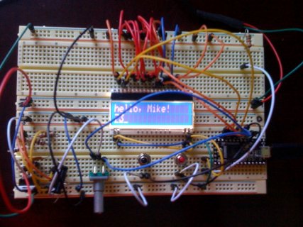
I am trying to emulate the Nav frequency sketch that Paul Has on his web site. All works well when I fire up Xplane and I can push button the frequency up and down ..not a problem. However, the encoder does not want to increment either way. My real problem is the display (DOG 163). it will not read. I have had this same circuit run from the arduino 2560 and wired up the 163 according to the 5V SPI recommendations. …….run the "hello world" sketch and i get "hello world"..(looks good..no backlight)
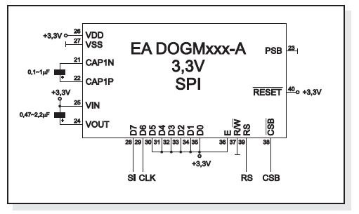
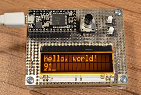
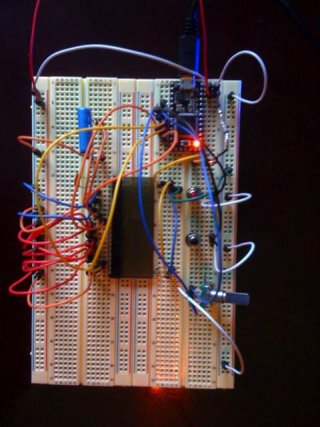
Now when i wire up the Teensy 3 & power it up using 3.3 volts... I wire it with the recommended 3.3 SPI wiring …..that is to say I am now incorporating those two caps you see in the pic. The little .1 microF is jumped across 21 & 22 on the LCD…….and the 1 microF ….is bridging lcd pins 24 and 25 as it goes to 3.3 volts.
That little resistor you see is the limiting resistor @ 2.2 ohms (even though I do not have the LCD(backlight module) in this setup. (had a 68 ohm with 5v & it was ok)
I am picking up the 3.3v supply from that big red wire next to AGND……..and GND off of AGND.
doing something wrong as I can not even get the "hello" to show up…don't mind the blink sketch in the pic…i use it to make sure the board is healthy


