Help with custom hardware for OctoWS2811

Status
Not open for further replies.

potatotron

Well-known member
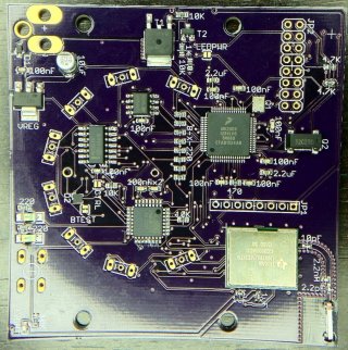
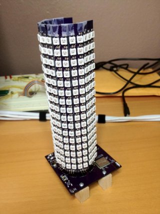
I'm trying to design a light based on OctoWS2811 and a custom Teensy 3 circuit. I've attached some pictures to give you an idea of the design.

When the LED boards are plugged in to a breadboard with just jumper wire, 6 or 7 of the boards work fine and 1 or 2 will flicker and not light up the correct LEDs. If I add 220 Ohm resistors all work fine with no issues.

When they're in this board two of them flicker constantly and one flickers intermittently, just like the breadboard with no resistors. But this design has the resistors, they're immediately to the left of the MK20 (labeled "8-x-220").

I'm sure this is a noise problem but I'm a software guy and don't know how to fix that kind of a problem. So...does anyone have any ideas of how I can fix this?

Thanks in advance for any help.
 

Attachments

  • PCB_Detail.jpg
    PCB_Detail.jpg
    230.2 KB · Views: 257
  • Side.jpg
    Side.jpg
    101.1 KB · Views: 592
I haven't tried a logic-level shifter -- it wasn't necessary in the breadboard prototype and the PCB is the same schematic so I didn't think I'd need it. I can try with the next revision, if I have to.

I think you might be on to something with using smaller resistors -- I found an impedance calculator online and if I'm using it correctly the traces are about 110 Ohms. I'll try it.

I don't have a scope or logic analyzer but if smaller resistors don't work I'll probably have to get one to see what's actually happening with the signals. Thanks for your input.

Did you ever get yours working? I have a very similar issue where my breadboard prototype works, but with direct connections it completely glitches out or doesn't light up at all. The strange thing is that when I connect a scope or multimeter to it, sometimes that magically makes it work.

I'm completely stuck and under a deadline. :-\
 
I actually spent today working on this. I don't have it working yet, but I'm getting closer.

I think the problem is an impedance mismatch; to cancel reflections etc. you want to size the resistors so they match the impedance of the wire between the MK20's pins and the Data In of the first WS2812 chip. I used an online impedance calculator (http://emclab.mst.edu/pcbtlc2/microstrip/) and found I should be using resistors of about 100 Ohms (as flyG suggests above).

I replaced all 8 resistors with 110s (the closest SMD I had) and now 7 of the 8 bars are working. I believe it would have worked for the 8th bar but the copper trace for that line meanders a lot so it's probably still picking up noise from something else (I let the autorouter do everything, which in retrospect wasn't the best idea...)

My guess is you're seeing the same thing -- when you connect a probe you're changing the impedance of the wire enough to attenuate the noise. Have you tried other resistor values? The WS2812 datasheet says to use 33 Ohms so try anything between 33-220 and see if it helps.

I'm now working on another revision of the board where I've replaced the 8 discrete resistors with a chip array and manually routed & widened the traces to the board headers (see attached). I going to try to have it off to Osh Park tomorrow and have ordered some more Mini54s from PJRC so hopefully I'll be able to have this one up by the end of the month.

Screen Shot 2013-10-12 at 6.30.09 PM.png

(edit - typos)
 
Last edited:
I'm pulling my hair out here. :(

I've tried every resistor between 10 and 4.7k. The only way I can get it to actually work is to put the multi meter across the signal and ground, unless the multimeter is measuring resistance, then I have to switch it to voltage and it starts working.

The only other thing that worked, and this is bizarre, was to have a 330ohm resistor that I had just barely soldered into the teensy, and barely soldered the signal wire to the other end of the resistor. Then I took a 6" breadboard jumper and touched it to either side of the resistor and the neopixel strip started working. I'm completely confounded.
 
So I've kind of gotten it to work by putting a 25v 1kuf cap at the supply terminals, but only when i plug the power supply barrel in very very carefully and slowly. If I do it too fast the strip starts and then freezes immediately with a few pixels lit. Also, even if I successfully have it running, if I update the code, the strip stops working until I remove power and carefully re-insert it again. Anyone have any ideas?
 
This is just a random guess, but sometimes problems where the project works with test equipment connected and fails with the gear is not attached have turned out to be grounding problems. Every project is a bit different, but the common theme usually involves a poor or missing ground connect to the Teensy. When the test gear is connected, the Teensy gets a better ground connection through the test, allowing it to work. Usually this happens more with oscilloscopes, function generators and other gear that gets AC mains power, not battery powered multimeters. Still, maybe it's worth mentioning?

Multimeters try to output a small test current when in resistance measuring mode. They'll create a small voltage, but usually it's limited to a safe level, and of course the test current is limited.

If you're seeing things work with that connected, maybe there's some sort of noise or other terrible signal corruption happening before the Teensy begins running your program. These LED strips shouldn't "remember" anything for more than 50 microseconds. Two things to try are first setting the pins to output mode and add a 100 ms delay before you start the library running. That will hold the line low for a brief time. Another thing to try might be adding a 4.7K resistor from the pin to ground. Again, these are just random guesses based on only the limited info posted here. I have no idea if they'll really solve your problem, but maybe it's worth a try?
 
Thanks Paul, I'll give those a shot.

I've also got some logic level converters on order that I'm going to try out as soon as I return home. I have one of the strips and a Teensy with me on the road though and a variety of resistors. Will play around with it some.
 
Status
Not open for further replies.
Back
Top