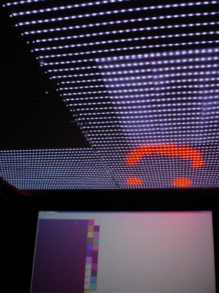
My OctoWS2811 / WS2812B Project - just looking for a "sanity check" and a answers
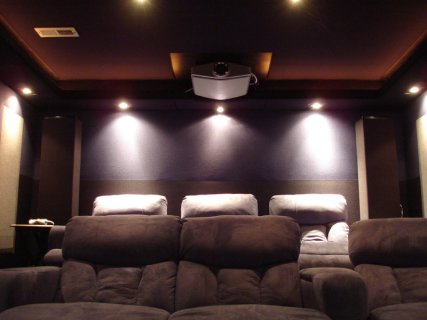
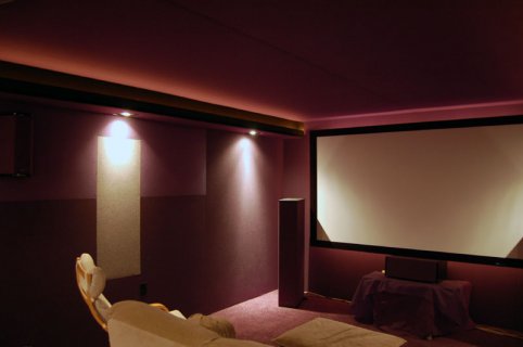
The basic concept: home theater ceiling lighting array to maximize ambient light with minimal impact to on-screen contrast. They will be on during "game nights" or other events where higher ambient light is desired, but off for movies.
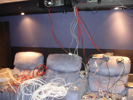
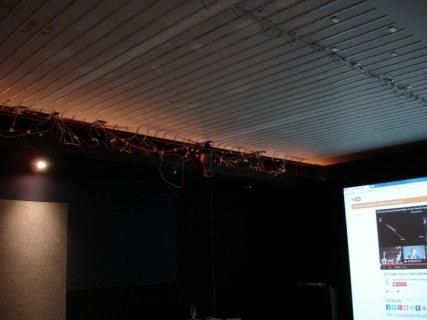
Note: I've already got about 1/8th of the overall project complete/installed as a test, but before I go all the way down my current path, I thought it would make sense to share w/ the community here in case I've missed something that's going to bite me
This installation will be behind black acoustically transparent wall-rated (fire resistant) fabric on a home theater ceiling. This acts to diffuse the light somewhat and also allows for the room to be "blacked out" entirely when the lights are off (to give you an idea of the weave, IR remote signals are able to pass through reliably). The system will allow cross-ceiling gradients and positional "bright" spots, e.g. LED's nearer to the screen will be dimmest so that the image is not washed out, LED's directly over seats will be brightest. RGB LED's will allow for correction of color temperature for "white" at various brightness levels as well as overall "scene" color, while the individual addressing will allow for the over-seat "spot" control. Scene creation or real-time control will be done via web UI, while basic scene recall (on/off) will be done via insteon.
Here're the specs/highlights:
Final layout ended up being 84x62, minus a 22 x 8 chunk, totaling 5032 LEDs.
[/edit]
Due to the arrangement of the LED's and the fabric system I'm using on the ceiling, there are strip "segments" of 41 LED's each, so the arrangement is something like:
41 LEDs x 4 segments == 1 164-LED strip
And the overall ceiling layout is essentially comprised of 2 by 14 of the above 41x4 strip arrangements, with each 300W PSU driving 4 or 5 41x4 strips. I picked the 300W units because the fans in the bigger MeanWell PSUs were so loud I could hear them even if placed outside of the sound-treated theater.
So here are the questions that are rattling around in my mind:
Comments, suggestions, and constructive criticism all welcome!
The basic concept: home theater ceiling lighting array to maximize ambient light with minimal impact to on-screen contrast. They will be on during "game nights" or other events where higher ambient light is desired, but off for movies.
Note: I've already got about 1/8th of the overall project complete/installed as a test, but before I go all the way down my current path, I thought it would make sense to share w/ the community here in case I've missed something that's going to bite me
This installation will be behind black acoustically transparent wall-rated (fire resistant) fabric on a home theater ceiling. This acts to diffuse the light somewhat and also allows for the room to be "blacked out" entirely when the lights are off (to give you an idea of the weave, IR remote signals are able to pass through reliably). The system will allow cross-ceiling gradients and positional "bright" spots, e.g. LED's nearer to the screen will be dimmest so that the image is not washed out, LED's directly over seats will be brightest. RGB LED's will allow for correction of color temperature for "white" at various brightness levels as well as overall "scene" color, while the individual addressing will allow for the over-seat "spot" control. Scene creation or real-time control will be done via web UI, while basic scene recall (on/off) will be done via insteon.
Here're the specs/highlights:
- approx 4500 leds (82x56 matrix, but some rows are not full 82 LEDs)
- spacing between each "row" of 82 pixels is 7cm OC, so it's not a true grid and wont be used to display images, video, or text
- 4 teensy 3.0 boards, each running in a 164 LEDs per strip configuration (1312 configured pixels per teensy 3.0, though the 3rd and 4th teensy will actually have fewer LED's)
- Beaglebone Black controlling them via USB
- 6 300W 5VDC MeanWell Power Supplies running on a dedicated 20amp 120v circuit
Final layout ended up being 84x62, minus a 22 x 8 chunk, totaling 5032 LEDs.
[/edit]
Due to the arrangement of the LED's and the fabric system I'm using on the ceiling, there are strip "segments" of 41 LED's each, so the arrangement is something like:
41 LEDs x 4 segments == 1 164-LED strip
Code:
*****************************************
                                         |
*****************************************
|
*****************************************
                                         |
*****************************************
And the overall ceiling layout is essentially comprised of 2 by 14 of the above 41x4 strip arrangements, with each 300W PSU driving 4 or 5 41x4 strips. I picked the 300W units because the fans in the bigger MeanWell PSUs were so loud I could hear them even if placed outside of the sound-treated theater.
So here are the questions that are rattling around in my mind:
- Am I asking for trouble (e.g. ground loop or similar) with 6 PSU's and 4 teensys?
- The first 164*8 combo tested beautifully on my workbench, but once up on the ceiling, I suddenly had flicker. All that changed was that 8ft of (probably-crappy) 22AWG LED "extension" wire was added between the PSU+Teensy and the strip and will be re-testing with 16AWG as soon as I get some, but is there anything else I should be checking if the thicker wire doesn't help?
Note:I am using a 74HCT245 with each Teensy - I don't need high refresh rates, nor do I need the Teensy's to be in sync (I'm not using the VideoDisplay code nor the 'video sync' pin - i'm just using the basic setPixel() and show() functionality). I have no complaints about the performance of one Teensy running 1300 LEDs, but is there any other reason I might want more boards?
- if I add resistors in addition to the 74HCT245, do they go between the Teensy and the 74HCT245 or between the 74HCT245 and the strips? I confess, I don't understand how additional resistance is helping reduce interference, so I'm just following signal quality suggestions on the Octo library page
Comments, suggestions, and constructive criticism all welcome!
Last edited:


