OBD/K-Line Buffer Circuit

Status
Not open for further replies.
I finally had some time to work on this again. I made several changes to the OBD9141 class I mentioned in my previous post. It now uses a begin() method, making it much easier to work with. I modified the examples such that they work out of the box and added an example for use with Arduino UNO, making use of the AltSoftSerial library.

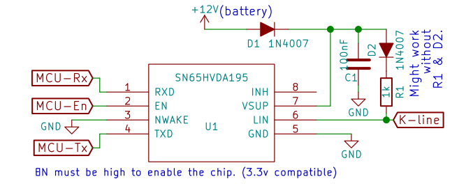
I also took the time to describe to create the schematic which I use, this is the main reason of this post. The circuit uses the SN65HVDA195-Q1 from Texas Instruments:
OBD9141_reader_cutout.png

For my car the R1 & D1 components are not even necessary, the IC is 3.3v compatible so no level conversion is required to hook it up to a Teensy. I hope this helps those looking for information on this in the future, this IC is still marked as 'active' at the time of writing.
 
That TI chip looks good. I want to try that out.
Can you guys recommend any libraries?
 
Can you guys recommend any libraries?
I'll bite; The most commonly known project which deals with the OBD port is to the best of my knowledge the opengauge / obduino project, the original project page is probably obduino.ca (OBDuino has a wikipedia page), source code ported from google code to https://github.com/magister54/opengauge. However, one can hardly speak of a library, there is some code which deals with the raw K-line initialisation, for example around these lines. But most people tend to use the ELM327 style chips which deal with the initialisation and provide a serial interface to request data from the car. Sparkfun's board for example also uses a ELM327 compatible IC (stn1110) to deal with the low-level communication, they then provide a command list and point you towards other programs for interfacing with this chip. I believe most people go down the ELM327 road, but there are few exceptions, for example this post describes a project on reading the OBDII port with an Arduino, but I could not find his code, there is some in his slides though.

So, (to the best of my knowledge) there isn't (wasn't) really a stand-alone library around which deals with the low level communication of the 9141-2 bus. This has led me to write my own library; OBD9141 it's a class which does exactly what I wanted :p It only deals with the communication with the bus and does nothing else besides that, it's pretty barebones but works well for me. Although the bus specification states that you should wait between sending bytes my car happens to return the entire answer with the bytes consecutively without delay. Because you know the amount of bytes that will be returned when you request a PID I use the readBytes method in order to read them without delay. This allows me to query about 20 PID's per second on my car, but your results may vary of course. I also wrote a simulator to aid in debugging, but it's not all that well tested, especially the handshake simulator is still a bit buggy, but when you both the simulator and the reader to 'initalised' reading PID's works fine, so for debugging a gui or something it should work. If you happen to try my library and have to incorporate additional handshakes (the fast init for example) feel free to send a pull request. In order to aid debugging your hardware I uploaded some recordings with a logic analyser of my K-line, both with a cheap Bluetooth OBD reader and with my library.

With the shameless plug done, if anyone else knows of another library to aid communication with the ISO9141-2 port, I'd love to hear about it. I hope both of you get your readers/loggers working!
 
@iwanders: Big thanks for the in-depth info! Your library looks good for what I intend to tinker with, I also have to look into fuel level and find the pID for my car (maybe, since not all cars support it).
Have you also tried a simple call to get error codes and possibly erase them? I have only done stuff like this with the ELM, but I'm not a huge fan of the "all-in-one" ELM. I think individual electronics/scripts work better for certain OBD protocols.
 
Last edited:
I also have to look into fuel level and find the pID for my car (maybe, since not all cars support it)
The wikipedia page OBD-II_PIDs is quite helpful in this regard. But I have to agree, not all cars support the same PID's, mine does not support the fuel level like you mentioned. I thought this was peculiar, but closer inspection of the workshop manual revealed that the fuel sensor is not even connected to the ECU, instead it goes directly to the dashboard :/ Be sure to use the 0x20, 0x40... etc PID's to check which ones your car supports, if I query a non-supported PID on my car I have to reinitialize the bus.

Have you also tried a simple call to get error codes and possibly erase them?
No I haven't, the last time I had the malfunction indicator I wasn't as far as I am now with this project. But I am certain you could read them, all you have to do is request mode 03 which returns the problem codes and mode 04 can be used to wipe them. One slight problem with this though, mode 03 returns a variable length of bytes, there is currently no method available which supports a variable number of answer bytes. Reading on wikipedia shows that you actually should not send a PID code for mode 03, I guess there should be a method like request() which allows reading a variable number of bytes. I added an issue to the github repo as a reminder, next time I'm working on it and have a test situation on my bench I'll try if I can quickly implement this.
 
Awesome. Will definitely play around with it when the SN65's arrive. Almost the same pin layout as the TI CAN chips I use so it should be an easy conversion.
 
I'm testing out the setup, not in a car yet, I have the hardware on a 15V bench supply per schematic above (without the 1k resistor).
Is it normal that I can measure 2.0V on the Kline pin against ground or do I have the wrong diode (I got the 1N4007)?
 
I'm testing out the setup, not in a car yet, I have the hardware on a 15V bench supply per schematic above (without the 1k resistor). Is it normal that I can measure 2.0V on the Kline pin against ground or do I have the wrong diode (I got the 1N4007)?
The diode should be alright, I also use 1N4007's. I presume you mean you left out both D2 and R1? With those left out, so only Vsup (12v for my test) powered through a 1N4007 (D1 that is), floating pins on the MCU side I measure 8v on K-line. With the EN pin at 3.3v I measure 0.63V on the K-line (again without the D2 and R1), when using 15v instead of 12v I still measure about 0.6v on the k-line. With Vsup floating and only the MCU connected I measure about 1.8v on the K-line.

However, in this situation there is no pullup or pulldown on the K-line so I doubt whether measuring the K-line voltage level in this situation really says anything... I for one wouldn't worry about it, the low-level voltage for the sn65hvda195-q1, is between 0v and 0.2*Vsup, so with 15v it is between 0v and 3.0v, you measure 2.0v so I'd say that's acceptable.
 
Thanks. I'm just being careful because I may have fried a teensy and the 12V line to the SVN could fry the teensy (in my layout).
I also shorted EN with Nwake (3.3V) because the chip is in place of where a CAN chip should be. The pads are similar, but not exactly the same.
 
Ok so the problem was that there was 10V on INH, which I unfortunately had connected to a Teensy pin. Overlooked the INH, oops.

Edit: Looking at the datasheet, it seems that Nwake can float or be permanently grounded, as long as EN is high, correct?
 
Last edited:
Looking at the datasheet, it seems that Nwake can float or be permanently grounded, as long as EN is high, correct?
I'm not entirely sure about this, the paragraph on the Nwake pin states: "NWake is a high-voltage input used to wake up the SN65HVDA195 from low-power mode. NWake is usually connected to an external switch in the application. A low on NWake that is asserted longer than the filter time (tNWAKE) results in a local wakeup. NWake provides an internal pullup source to VSUP." I just grounded it to ensure that the IC never sleeps, but paragraph 9.4.3 9.4.4 state that you can wake up the device from sleep by setting EN high, despite Nwake being high?

When looking at the typical application circuits, they use the NWake pin for an external switch to enable or disable the device. But the EN pin seems to be able to do that as well using a 3.3v instead of a high voltage level, which led me to ground the pin to prevent the IC from going to sleep. Reading the datasheet again I'm not all that sure whether that's the best practice.. although they state there is an internal pullup on this pin in section 12.1 they put: "If the NWAKE local wake-up feature is not used, the pin can be tied to VSUP through a 1-kΩ to 10-kΩ pullup resistor." So perhaps it's better to give it a pullup of 4.7k to disable the local-wakeup functionality if the enable pin is used? The most ideal would be to measure what happens I guess, I pulled it down and it works fine but it might not be the recommended solution. If you happen to test it with a pullup or floating, please let us know what the effect was.
 
Hello everyone, my name is Jakub.
I’m writing with one big question: can anyone help me with connecting Arduino Pro Mini to the OBD II in VW Sharan from 2001r. as far as I know it has K-line ISO 9141 Protocol. Everyone here is writing about Teensy 3.0, but is it the same thing as Arduino? If yes then what is the best way to start reading date from my car? I am looking all over the web searching for a good guide but with no luck. There is one Russian forum: http://www.compcar.ru/forum/showthread.php?t=4992&highlight=OBD2 where I can see a MC33290 connected to the K-line and some kind of microcontroller, plus there is a code that looks like can be used in Arduino.
The project that im working on is to use my Arduino as a translator from the K-line of my car and my Alpine radio. I want to use the steering wheel buttons to operate my new radio. I have written the code that can talk to Alpine radio, sending commands like: VolUP, VolDown, NextTrack etc. but I can figure it out how to read the steering wheel buttons… :( Is there any way that I can scan the whole K-line Protocol to search for those buttons? If yes, the can someone give me a hand with that?

P.S. Sorry for my English :(
 
Everyone here is writing about Teensy 3.0, but is it the same thing as Arduino?
This is the Teensy forum, so it makes sense that everyone is writing about it. The Teensy is a development board with a microcontroller. So the Arduino and Teensy fit in the same category, but they are not the same thing. The newer Teensies use a 32 bit ARM microcontroller, whereas the Arduino uses an 8 bit AVR chip. So how they work is different, but they can fulfill the same task. Thanks to Paul's hard work most code that runs on an Arduino also runs on a Teensy without modification. So you could see it as an alternative to an Arduino, with more peripherals, ram and speed but the same ease of use.

I am looking all over the web searching for a good guide but with no luck. There is one Russian forum: http://www.compcar.ru/forum/showthread.php?t=4992&highlight=OBD2 where I can see a MC33290 connected to the K-line and some kind of microcontroller, plus there is a code that looks like can be used in Arduino.
I agree guides are a bit scarce. I believe there is a few threads over on the official Arduino forums. There are various blog-posts around the internet, for example http://rvmiller.com/2010/12/arduino-obd-ii-interface/, his writeup and presentation should provide you with some information to get going. But in general there is not much more to it than connecting an interface IC and programming your microcontroller. The diagram on the page you linked should work, the code on that page is indeed Arduino code, the micocontroller there is something like an Arduino Nano. There's also some information on the wiring and such at the github page of my library: https://github.com/iwanders/OBD9141.

but I can figure it out how to read the steering wheel buttons… Is there any way that I can scan the whole K-line Protocol to search for those buttons? If yes, the can someone give me a hand with that?
I think this is going to be quite tricky, K-line is most often used to communicate to the ECU (Engine Control Unit), for diagnostics and measurements. I have never read about a car where it is also used for buttons and auxiliaries. If the car has a CAN Bus, that bus is likely to be used for the buttons, but I'm doubtful whether K-line is ever used to send signals from buttons. I'd check whether the buttons on the steering wheel are actually connected to the K-line, before trying to build an interface circuit to read the K-line. Perhaps you are best off wiring those buttons to an Arduino or Teensy and then interfacing that to your radio.
 
I agree. Even in CAN cars there's a good chance you'd have to be communicating with the entertainment bus itself.
Entertainment buses aren't very new, I have doubt a 2000-ish car would have one, but I'm not familiar with VAG and I'm sure the info can be found online either in the car's electric schematics or schematics/pinouts for the particular radio.
The easiest/fastest way would indeed be using the Teensy as an interface between the buttons and radio electronics. Even if you do find info on whether it communicates over CAN or K-line, you would still have to decode the messages, if not readily available online, which can be a tedious process. Generally though, in 2000-2005 the buses in cars were mixed in various ways and sometimes proprietary (proprietary buses alongside automotive standard buses), which makes this harder. Newer cars are basically fully CAN bus capable and buses are sometimes divided into parts of the system on different OBD port pins (safety bus, ECU bus, entertainment bus) making it a little easier.
 
Thanks for your help. I have finally finished this product :) unfortunately I wasn't able to read the stearing wheel buttons without any modifications so I had to add some changes. I have added to each button an extra resistor so by using just 2 wires (one connected to the GND and the second one to analog pin) I can read 4 different values, then I can convert them to the Alpine code so I can operate the radio :)
Here is a link to the video https://vimeo.com/154428244
 
Status
Not open for further replies.
Back
Top