Read RC Reciever with Teensy 3

Status
Not open for further replies.
Great!

FYI - if you are trying to read in pulses from a receiver, I still don't think pulsIn is the best route... Can eat up lots of time.
For the fun of it I dug out my Turnigy RC... and first trying it out on T3.2 (Will try on T3.5 later).
Simple Sketch:
Warning changed pin 2 to 8 (think 2) as pulseIn(2,HIGH); was failing probably bad solder...
Code:
uint8_t RC_Pins[] = {0, 1, 8, 3, 4, 5, 6, 7};
//uint8_t RC_Pins[] = {0, 1, 4, 6, 8, 3, 5, 7};

#define RC_PIN_COUNT  sizeof(RC_Pins)
uint16_t pws[RC_PIN_COUNT];
uint32_t dts[RC_PIN_COUNT];

void setup() {
  // put your setup code here, to run once:

  for (uint8_t i = 0; i < sizeof(RC_Pins); i++)
    pinMode(RC_Pins[i], INPUT);

  uint32_t start_time = millis();
  while (!Serial && ((millis() - start_time) < 5000)) ;
  Serial.begin(115200);
}


void loop() {
  // Get set of Pulse widths
  uint32_t ts_loop = micros();
  
  for (uint8_t i = 0; i < sizeof(RC_Pins); i++) {
    uint32_t ts = micros();
    pws[i] =  pulseIn(RC_Pins[i], HIGH);
    dts[i] = micros() - ts;
  }

  uint32_t dt_loop = micros() - ts_loop;
  Serial.printf("%d : ", dt_loop);
  uint32_t dt_sum = 0;
  for (uint8_t i = 0; i < sizeof(RC_Pins); i++) {
    Serial.printf("%d=%d(%d) ", RC_Pins[i], pws[i], dts[i]);
    dt_sum += dts[i];
  }
  Serial.println(dt_sum);

}
With the Receiver on, you see the output looking like:
Code:
58646 : 0=1477(9218) 1=1479(2774) 8=1290(18228) 3=1482(2966) 4=1292(2780) 5=1483(18415) 6=1482(2779) 7=1483(1484) 58644
58653 : 0=1476(9224) 1=1479(2775) 8=1291(18228) 3=1482(2964) 4=1292(2779) 5=1483(18416) 6=1482(2779) 7=1482(1484) 58649
58652 : 0=1476(9222) 1=1479(2774) 8=1290(18230) 3=1483(2965) 4=1292(2779) 5=1482(18416) 6=1483(2779) 7=1482(1484) 58649
58652 : 0=1476(9220) 1=1478(2773) 8=1291(18230) 3=1483(2966) 4=1293(2780) 5=1483(18414) 6=1484(2779) 7=1483(1485) 58647
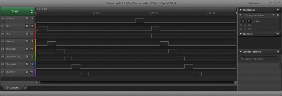
So it is taking on average about (58ms to get the 8 channels, if I use the straight order. (3 cycles)

Hooked up to Logic Analyzer you see the pulses:
screenshot.jpg

But if you change the order, you can drop the time:
Code:
38940 : 0=1477(9222) 1=1479(2774) 4=1292(4264) 6=1483(1485) 8=1290(12478) 3=1483(2966) 5=1483(1484) 7=1483(4264) 38937
38945 : 0=1477(9228) 1=1478(2773) 4=1292(4264) 6=1483(1485) 8=1290(12480) 3=1482(2965) 5=1484(1485) 7=1483(4264) 38944
38946 : 0=1477(9227) 1=1478(2773) 4=1292(4264) 6=1483(1485) 8=1290(12480) 3=1483(2967) 5=1483(1484) 7=1482(4263) 38943
38944 : 0=1476(9224) 1=1479(2774) 4=1291(4264) 6=1482(1485) 8=1291(12480) 3=1483(2965) 5=1483(1485) 7=1483(4263) 38940
38947 : 0=1476(9225) 1=1479(2774) 4=1291(4263) 6=1483(1484) 8=1290(12481) 3=1483(2966) 5=1482(1484) 7=1484(4264) 38941
38946 : 0=1476(9223) 1=1479(2774) 4=1291(4262) 6=1483(1484) 8=1291(12482) 3=1483(2966) 5=1483(1485) 7=1483(4265) 38941

Or about 2 cycles... Again not great, but... Next up may play with Attach Interrupt.
 
I'm finding this pulseIn() to be very finicky? Haven't figured out why - my simple prior sample gave the results I expected. As I added a bit more to count the times it fails to register a pulse - with the ISR() clocking the bit - it gets worse. Since I was counting I sped it up to get results faster - but with the pulse wait 2.5 times the current ISR timer it will often fail 6 times in a row - I suppose it is just a sync issue as after each test it won't retest for a fixed tim e- but in 2.5 times the ISR it should always sit through a full HIGH/LOW/HIGH cycle?

I need to start couting the ISR hits perhaps - the USB output is interfering? Just a puzzle if I get cleaner code with some consistent results I'll post.
 
I'm finding this pulseIn() to be very finicky?

I used the little sketch I had in post #22 to compare attachInterupt() with pulseIn() a while back, because on another project I had experienced a lot of jitter with pulseIn(). attachInterrupt() was better. For tiny width pulses, attachInterrupt() is limited by ISR overhead. As Paul noted, there is PulsePosition, and FreqCount/FreqMeasure*
 
Last edited:
I used the little sketch I had in post #22 to compare attachInterupt() with pulseIn() a while back, because on another project I had experienced a lot of jitter with pulseIn(). attachInterrupt() was better. For tiny width pulses, attachInterrupt() is limited by ISR overhead. As Paul noted, there is PPMout, and FreqCount/FreqMeasure*

Thanks - I just looked at your code again - I had missed loopx() before showing MyISR() usage. That is very clean and nice!

I don't have any need for this - but I'd like to see why my working example gets toasted so easily! Partly no doubt is the ISR() fight since I'm using Timer1 to create my Pulse - and doing it on a time limited trial on an elapsedMicros() each 50ms. Maybe I should make a volatile gate variable on my toggle and turn it on only across the PulseIn() call. I'm also updating "Timer1.initialize(TimeVal);" to a new value after every successful Pulse read (In the range of 1021us to 2500us), but it was working - and works again if I strip out my extra instrumentation code - I can leave some essential prints but can't count the success versus fails - even if I don't do and print the math faster than 10 seconds or not at all.
 
As for failures now... If it were me I would probably add some more debug code...

Probably something like: See how long each of the pulseIn statements is taking, example of this is in posting #28, where you can see the value of pulseIn and a delta time it took for pulseIn to complete.

My next step would be with the failures is to use my logic analyzer... For example bracket the call like:
Code:
digitalWriteFast(0, HIGH);
PulseIn(...)
digitalWriteFast(0, LOW);
I would probably also add a toggle of another IO pin in failure cases, and then I would hook up Logic Analyzer and watch the pin I was doing the PulseIn on, plus the one or two debug pins...
 
Maybe you're thinking of PulsePosition? It's meant for reading a PPM stream, which is the encoding of many RC signals on a single pin. It's able to read several of those.

http://www.pjrc.com/teensy/td_libs_PulsePosition.html
Yes - that was what I was referring to earlier as the preferred method of timer capture input...

Since I have an RC receiver out to play with, sounds like an interesting test setup to try using the 8 FTM0_CHx pins, which I would believe the code should measure 1 channel per each... Then try on T3.5.

Update: playing with PulsepositionInput, but it won't work directly for this. I am pretty sure it is more likely to be setup to handle something like:
Hitec-laser6-logic-scan.jpg
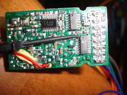
Bottom line, was where I hacked a Hitec receiver, to get the signal:
Hitec-laser-6-receiver.jpg
Maybe at some point I will try out that receiver, but for this test, I think I will try making a modified version of the library that reads in the single pulses.
 
Last edited:
UPdate again: As I mentioned in update to previous post, the PulsePositionInput code will not work for simple RC receiver... So I hacked up a different version of the library, which does capture on leading edge, then change edge to trailing edge, does capture and return the delta...

The hacked up code is in the sketch (two new tabs): View attachment RC_Receiver_Attach_PulsePosition-160705a.zip

If this is something of interest, could merge back into PulsePosition library...
 
Status
Not open for further replies.
Back
Top