Measuring crystal frequency (Eurorack frequency/tuning module)

Status
Not open for further replies.

Nantonos

Well-known member
I'm working on a frequency measuring project for a modular synthesizer, using FreqMeasure and FreqCount libraries on a Teensy 2.0. Since I now have a multimeter that claims frequency measurement from 10Hz to 400Mhz +/-(0.01%+8) (UT71C) and since I also have voltage/current/resistance/frequency standard (see below) to check those claims, I was wondering where on Teensy 2.0 to measure the exact crystal frequency.

Given the pair of small capacitors around the crystal itself, I assume that putting probes directly there would be a bad idea, at minimum altering the frequency and possibly doing damage. Should I instead run some code that toggles an output pin such that it depends directly on the crystal frequency, measure that, and calculate the crystal from that? Or I guess, build the unit, have it measure the two frequency standards and calculate a correction factor from that. (Amazing how explaining a problem clearly for a forum posting often leads to the actual answer. But I'm going to go ahead and post anyway). Suggestions welcome.

My project will use two Teensy 2.0, one handling the user interface (buttons, display, input switching, calculating derived values) and also temperature measurement and oven control; the second will be in a constant temperature oven with a separate, highly regulated power supply to minimise voltage-related and temperature-related fluctuations. But the absolute value of the crystal (at that temperature and with that supply) still needs to be measured. (The temperature probe is a Dallas DS18B20 One Wire Digital Temperature Sensor and the display is the Adafruit 0.96" 128x64 OLED which has been recently discussed in these forums, regarding use with hardware SPI on Teensy 3.0. This will be a Eurorack module).

The standard reference I mentioned is the DMM Check Plus by voltagestandard.com. In addition to using burned-in, high quality components it also comes with an individual measurements sheet, measured with an in-calibration HP 3458A and, for the frequency, an Agilent 53220A.
My particular DMM Check Plus unit has two frequencies, 439.968356 Hz and 7.042592 kHz.
 
Should I instead run some code that toggles an output pin such that it depends directly on the crystal frequency, measure that, and calculate the crystal from that?

Yes, that's the best way, if you have an accurate frequency counter and you just want to check Teensy's crystal.

Or I guess, build the unit, have it measure the two frequency standards and calculate a correction factor from that.

That sounds great, if you're building the frequency measurement with Teensy, rather than using some known-good instrument.
 
I presume the synthesizer is running audible frequencies, i.e. >16kHz?

I wonder whether you could use the Teensy 3 RTC input instead. The reason this might be interesting is that the Teensy 3 has internal capacitors that can be enabled / disabled through software. Thus, you get a lot of flexibility and less/no need to swap out capacitors to allow for different types of crystals.

The only obvious issue is how the Teensy 3 MCU would react to having a RTC in there that runs at less than 32Khz. I'd like to think that the MCU wouldn't care - but I'd have someone like Paul confirm that - or just try it out and see what happens.

As far as implementation goes, the manual isn't half bad, as long as you don't try to muck with the prescaler values [I'd disable the prescaler compensation]. You could then read the RTC registers directly and use a GPS receiver with a PPS output to capture exactly how many ticks a given oscillator / crystal has delivered to the RTC input over a period of time, let's say 10 seconds.

The GPS PPS signal gives you the accuracy of an atomic clock and the number of 'ticks' in the TSR register gives you exactly how many times the oscillator / crystal has ticked over. Seems like a pretty good way to do it. Thoughts?
 
In this github folder are some sketches and program for measuring the frequency drift of MCU crytsals and RTCs using both GPS pps and an NTP host. The file crystals.txt includes some results from various devices including exercising different capacitances for the teensy RTC.

https://github.com/manitou48/crystals

Frequency can vary with age, voltage, and temperature so you might wish to make thermal adjustments.
 
Frequency can vary with age, voltage, and temperature so you might wish to make thermal adjustments.

I totally agree…
PPM Error.png
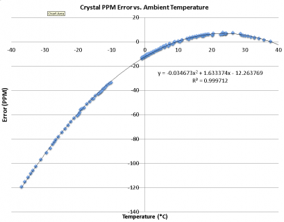
This graph shows temperature effects on a CFS206 crystal I tested.

Your code was a great inspiration, though I didn't end up using it - I was afraid that a interrupt-driven approach could lead to less consistent / accurate results vs. actively (and constantly) polling the PPS signal.

As I recall, there is a cost associated with dropping into a interrupt (~56 CPU cycles or about 1.5µs on the AVR?) so I simply used a while statement that polled the PPS input and captured the change as soon as it happened.

Thank you again for your work though, because without it I don't think I could have assembled the code that made the measurements above.
 
Last edited:
In this github folder are some sketches and program for measuring the frequency drift of MCU crytsals and RTCs using both GPS pps and an NTP host. The file crystals.txt includes some results from various devices including exercising different capacitances for the teensy RTC.

https://github.com/manitou48/crystals
Yes, I had seen that earlier although you have added more since. Its good to have two datapoints for the Teensy crystal.
teensy 3.0 16MHz*6 crystal 15ppm -5 NDK NX3225SA-16
teensy 3.1 16MHz*6 crystal 15ppm -18 NDK NX3225SA-16
I notice you don't have results for Teensy 2.0 or ++2.0 (though i understand all of the Teensies use the same 15ppm 16MHz crystal)

Frequency can vary with age, voltage, and temperature so you might wish to make thermal adjustments.
Yes, that was why I mentioned a separate regulated power supply (unaffected by fluctuations in draw of the other Teensy) and the constant temperature oven.
 
I presume the synthesizer is running audible frequencies, i.e. >16kHz?
I realise the phrase was ambiguous. I mean a synthesizer in the musical sense so yes, audio frequencies.

I wonder whether you could use the Teensy 3 RTC input instead.
Interesting idea, but the FreqCount and FreqMeasure libraries are currently Teensy 2.0 and ++2.0 only.

IThe GPS PPS signal gives you the accuracy of an atomic clock and the number of 'ticks' in the TSR register gives you exactly how many times the oscillator / crystal has ticked over. Seems like a pretty good way to do it. Thoughts?
That looks like a good way to measure long-term drift. For this application, short-term stability is more important. Drift also matters in terms of stability of calibration, but not in the sense of losing time relative to some master clock.
 
View attachment 1203
This graph shows temperature effects on a CFS206 crystal I tested.

That is a nice clear trend and could probably be used to calculate a temperature compensation. Its also good to see the curve is relatively flat at ambient room temperature to "a bit warmer inside a case" (40°C or so). But if I am measuring the temperature, its also easy enough to close the feedback loop by switching on and off heating (just some resistors) inside an insulated chamber.
 
Last edited:
...the FreqCount and FreqMeasure libraries are currently Teensy 2.0 and ++2.0 only….

Perhaps I'm a bit daft, but why use a library at all? Seems to me that if the Teensy 3 can do in hardware what the Teensy 2 is doing in software (using a library), that the better approach would be to use the Teensy 3, especially since the capacitance of the Teensy 3 RTC input can be adjusted through software.

IIRC, manitou varied those inputs for one of his experiments, confirming that Paul had chosen excellent values to minimize the clock drift of the main MCU clock.

The main caveat is whether the Teensy 3 would tolerate a non-32kHz crystal/signal on the RTC input or not. I'd try it out but I don't have any 16kHz, etc. cans banging around...

That looks like a good way to measure long-term drift. For this application, short-term stability is more important. Drift also matters in terms of stability of calibration, but not in the sense of losing time relative to some master clock.

You are absolutely right, using a PPS signal presumes a long time base and if you are concerned about the stability of short bursts vs. long outputs I can totally see why you'd want to take a different approach.

The above graph was assembled to see if I could compensate for temperature-related drift of the RTC. You could turn it around (with the help of a GPS) and use the the RTC crystal as a temperature sensor. The correlation (R2) was pretty high!
 
Last edited:
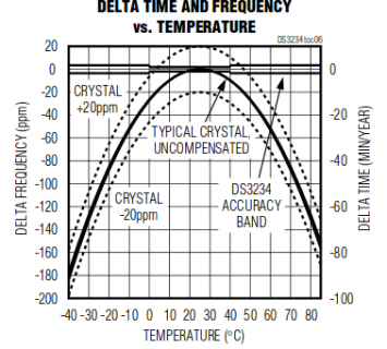
The trouble with GPS is your GPS antenna needs to "see" the satellites. Would a TXCO work? Most of the temp-compensated crystals run within 2ppm

tcxo.png
The TXCOs usually have a pps (or higher frequency interrupt). Examples like chronodot or sparkfun DS3234 are managed with SPI or I2C.
 
You are right, a GPS receiver needs a good signal. I was surprised how well the receiver worked in my home - first directly under the roof (EPDM+wood+Icynene) and later under two floors + the roof. On the other hand, at work, between a metal roof, an external overhang, and likely metallized windows, I had no luck getting a PPS signal and had to wheel everything out of the office.

If I had to do it at the office, I'd invest in an external antenna and use something like the "Ultimate GPS receiver" that Adafruit sells. It takes external antennas and/or you can run a coax wire to your oven with the PPS + GND signal.

I agree that the cronodot may be a really good candidate for your approach, Manitou - it features a 32.786kHz output that is good to +/- 2PPM. I like the DS3231 it uses, a very stable, easily programmed RTC. Additionally, it features a SQW output pin that can be useful as an external alarm trigger / timer pin.
 
Perhaps I'm a bit daft, but why use a library at all?

The main caveat is whether the Teensy 3 would tolerate a non-32kHz crystal/signal on the RTC input or not. I'd try it out but I don't have any 16kHz, etc. cans banging around...
Perhaps I am being daft in turn; but for measuring frequencies up to 20kHz with precision, it seems that there needs to be multiple clock ticks per period of the measured frequency; so a 16Mhz 15ppm clock is suitable but a 16kHz clock (even with a good 2ppm) would be quite unsuitable because it is way too slow?
 
Remember, I'm a manufacturing engineer…

So some of my suggestions may run rather counter to what is orthodox in EE circles. So no worries - here is what I suggest you could do:

  1. Attach the crystal / oscillator output to the RTC inputs of the Teensy 3 - obviously pay attention to voltage if its a oscillator.
  2. For crystals, set the proper capacitance using the RTC rgisters that control the on-board capacitors.
  3. Get a PPS signal via a GPS. Monitor status (HIGH, LOW) on a digital pin of your choice.
  4. When the PPS goes high (assuming you have reception), read the 'start time' RTC_TSR register.
  5. Delay about 300 ms to let the signal go low
  6. Wait for the PPS to go high again, then read the 'current' RTC_TSR register.
  7. Subtract the starting RTC_TSR reading from the current RTC_TSR (unsigned 32bit, IIRC) and you have exactly how many times the crystal swung in a second.
  8. Lengthen the time base to increase precision, but it should be pretty good
  9. The only caveat I can think of is: How will the MCU respond to a 'wonky' frequency input (i.e. something other than the expected ~32kHz).

As soon as Paul picks himself off the floor laughing at this suggestion, I'd love to hear what he thinks. For all I know, there is some deep connection between the RTC and the MCU clock cycle that makes the above approach unsuitable for anything but crystals oscillating at 32kHz.

That said, I see no reason why you couldn't replicate this approach using a interrupt, counter, etc. on any pin of the Teensy 3. The only downside of using a non-RTC input is that you can't adjust capacitance for the crystal in software - you'd have to do it manually instead. HTH
 
Last edited:
Status
Not open for further replies.
Back
Top