Using the VIN pin to ~supply~ power when powered by USB (instead of VUSB). Bad idea?

Status
Not open for further replies.

tetsuo

Well-known member
OK, so I confess that I'm looking to be lazy here. The t3.0 schematic shows a 500mA fuse I'm at risk of popping, but knowing that it draws very little current, I tried powering a 74HCT245 off of the VIN pin and it seems to work fine. I'm still using a 0.1uF cap between Vcc and GND as would normally would.

I know this clearly isn't the intent of the circuit layout and I should be using VUSB (which I did in my initial testing), but nothing in the schematic screamed "don't do it!" to me, and it's SO much more convenient to leverage VIN than VUSB as a +5V when the T3 is plugged into a breadboard! :D
 
This is perfectly fine. You can power 5V stuff from either VIN or VUSB. Unless you cut the little wire link on the bottom of the board, they're connected together.

The 500 mA fuse is actually a PTC device. Often these are called "self resetting fuses", and sometimes by one brand name "polyswitch". But physically, PTC's aren't truly fuses.

A PTC is actually a resistor that increases its resistance if it gets too hot. PTC stands for Positive Temperature Coefficient. Physically, it's made with metal particles suspected in a thin insulating material that thermally expands. At low temperatures, the metal particles mostly touch and form a fairly low value resistor. As it heats up, the material expands and reduces the number of metal bits in contact, so the resistance goes up dramatically.

Unlike a real fuse that stops current from flowing, a PTC merely becomes a larger resistor, which tends to limit the current to a (hopefully) safe level. Current continues to flow the whole time. The only thing that keeps the PTC "blown" is the continuous current that keeps the material hot enough so the suspected particles don't get close enough to allow good conduction, so the failure mode is a continuous current flow and not all current stopped as you'd expect from a real fuse.

Calling PTCs fuses is great marketing (mostly by Raychem) and conceptually, PTCs are used to prevent damaging current levels if you accidentally short wires. But they aren't actually fuses. When designing with PTCs, it's good to keep a mental model of a resistor that changes and avoid thinking of it as a real fuse. Of course, when the final product leaves engineering, it's advantageous to think of it as a fuse (which everyone understands) on the sales & marketing side.
 
I like how Paul separated the two, VIN and VUSB... I see two immediate reasons why, as it give the user the option to:

  1. Not use VUSB at all to power the voltage regulator on the Teensy 3 (because you don't want transients on the USB bus to interfere, optical isolation considerations, etc.) or
  2. You want to voltage regulate externally (i.e. not use the MCU for that purpose). That requires a cut to the VIN-"fused VUSB" line. You're still free to use the VUSB, however - For example, I use a dual Schottky diode to switch between VUSB and alternative on-board power sources automatically.

Regular USB buses are not supposed to be stressed more than 500mA unless the controller and the device 'negotiate' a higher current transfer rate. That's why a severely depleted iPhone will charge slowly at first, and charging only really takes off once the MCU is re-awakened. If the negotiation is successful, iPhone will be able bulk charge well in excess of 500mA on the right device. Hence the 500mA fuse - Paul is doing the right thing providing it to stay in USB-spec, and I'd use it too!
 
Last edited:
This is perfectly fine. You can power 5V stuff from either VIN or VUSB. Unless you cut the little wire link on the bottom of the board, they're connected together.

The 500 mA fuse is actually a PTC device.

Thanks Paul! I did check the schematic before-hand and the only thing I could see would be different in using VIN vs VUSB was that not-really-a-fuse fuse :D Good to know that if somehow I draw more than that much current it will give up with a self-resetting whimper instead of a terminal bang!

@Constantin - I had started with all power being provided externally, but with 6 PSUs and 4 teensies (and still needing to be connected to USB at all times for data, even though I wasn't using it for power), I was chasing down more grounding-related quirks. Powering off of USB cleared up a small handful of those issues for me.
 
One of the uses I have always envisioned for VUSB separated from VIN, but so far haven't actually used, it a LiPo battery charger board.

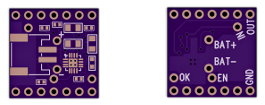
I actually have one in the initial design phase now, waiting for the first PCBs from OSH Park. It's half the size of a Teensy 3, meant to mount on top. It gets power from VUSB and automatically charges the battery when USB is connected, and the VIN pin gets supplied from the battery when USB is disconnected.

batcharger.png
 
One of the uses I have always envisioned for VUSB separated from VIN, but so far haven't actually used, it a LiPo battery charger board.

I actually have one in the initial design phase now, waiting for the first PCBs from OSH Park. It's half the size of a Teensy 3, meant to mount on top. It gets power from VUSB and automatically charges the battery when USB is connected, and the VIN pin gets supplied from the battery when USB is disconnected.

View attachment 1228

Well that's another piece I won't have to design and build. :D
 
Status
Not open for further replies.
Back
Top