Teensy 3.1 and CAN Bus

Hi, I've made a shield for CAN bus and power supply. It (should) have the same dimensions as the Audio Adapter.

Please review and tell me if you're interested.
Nice.

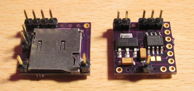
Here is one I've made some time ago (on the photo together with the MicroSD shield)

shields.jpg
 
I am interested in a CAN shield ... where might I get some of these? One concern with Manuel's is that his termination is 100 ohms, rather than the usual 120 ohms. Also, an isolated solution might be good. But, thanks to both of you for designing some solutions!
 
Wow, so many replies in a short time :cool:

PaulStoffregen said:
Looks interesting. Any thoughts about putting a 3 position terminal block on the board, maybe up on the top side?
I don't know exactly what you mean. What would be connected there?

dpharris said:
I am interested in a CAN shield ... where might I get some of these? One concern with Manuel's is that his termination is 100 ohms, rather than the usual 120 ohms. Also, an isolated solution might be good. But, thanks to both of you for designing some solutions!
The PCB can be ordered directly at 123d.circuits.io as soon as I mark is as "done". The 100 ohms resistor was my fault, will change it.
Just a thought - how about using the 3.3V regulator (and 3.3V transciever) to not stress the Teensy's internal regulator?
I want to power a USB device from the regulator. That's why I took a "big one". But the same regulator (same footprint) is also available as 3.3V version, so it's just a matter of assembly.
 
Great job by all involved. I have been following this thread from its inception. I only just recently got a teensy 3.1 and began bench testing for my CAN based switch panel project. I am able to successfully transmit on a 1Mb/s bus using the Microchip MCP2551. Is it possible to transmit from more than one base address or am I limited to only one and therefore just 8 bytes of data for transmitting? I have experimented with several approaches, and after digging through FlexCAN.h and FlexCAN.ccp, I am unable to reach any definitive conclusion. I am a mechanical engineer and relatively new to programming. Any pointers or input is appreciated. Thanks again to all of you.
 
Hi All,

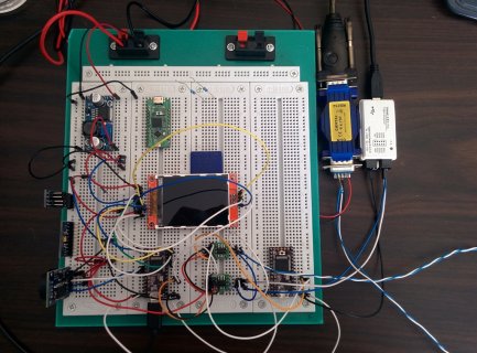
Finally got my setup working with two teensy's talking via Can (trancievers are a TI *232 on a SOIC8 breakout):

IMG_20141224_125643.jpg

There is a basic priority system reading messages generated on the bus and displaying them on the lcd.

I have a few questions about the mask format for the global mask, for example if I wanted to catch all ID's that were in the range 0x220 to 0x240 (32 frames).

on the MCP2515 there is a filter and a mask so I would set it like so:

Filter: 0b010 0000 0000
Mask: 0b111 1000 0000

Which would return all frames from 0x200 to 0x27F and block all others (I'm sure there is a more efficient mask but I don't have my spreadsheet) is there anyway to achieve this with the current implementation?
I've been hoping an example in the library might show how the filters are implemented.

Additionally is there any progress on an ISR vector that will be called on the filling of one of the FIFO buffers? I'm worried that too much traffic would start to overrun the current polling method to filter the packets you actually want. In the intended application the 1MBps bus is running at 70% utilisation.

Another useful feature would be a function or ISR that returns the current state of the bus, error flags and Rx/Tx Error counts.

Paul: I have a listen only example which I will add to the library for the next teensydrino release.
 
Nice work guys. I'm waiting for components to arrive so I can start a similar project. Just as Mr.CanBus I want to read enginedata from a Ducati. First goal is to just to be able to read out rear wheel speed and engine revs for calculate gear position. The final purpose is to make a system for logging more data , adding more sensors to measure tyre temperature, brake pressure and damper travel.
I'm thinking about ordering some of Manuel Stahl's can shield pcb layouts from 123D Circuits. Which Can transceiver should I go for, MCP2551 , MCP2561 or MCP2562?
 
Anyone tried sending a message to a motorcycle/car with positive results? Possibly example code?

I've personally had good experience reading using the MCP2551. Only "setback" is the 5V, so I made some 12-20V to 3.3V+5V adapters.
 
Last edited:
I've still not tried sending, only listening, but there are plenty of treads on other forum with people sending messages into the bus on cars without problems. The issue I forsee with my bike is that it sends messages constantly, e.g. BRAKE_LIGHT = OFF not just a message to turn it ON. I'd imagine if I tried to send a message in I'd cause some sort of conflict/error or at best make it flicker (in the brake light example). The solution would be to physically split the bus and filter out the unwanted originally message, replace with my own and 'pass through' all the other messages. But that would involve major surgery on the loom unless I could get hold of connectors to make up a new section of loom to plug and play. There was a kickstarter for something called "CANBUS Triple" that was built specifically for this purpose.

Let me know how you get on if you try.
 
I wanted to post to thank everyone who worked on getting the canbus drivers for the teensy3.1 completed. I am working on a project which uses two teensy3.1's working together to implement 4 wheel steering on an industrial platform and was able to use the canbus drivers for tennsy3.1 to teensy3.1 communication. Eventually I want to add a routine to receive canbus data from the microsquirt engine controller to display on the 4d systems LCD I am using for a dash. I could not have gotten this far with out your help.

Mark

BTW this thread sure went dead lately.
 
Can anyone confirm if this would be the correct way to format a message?

Code:
void CAN_Send(){

  msg.id = 0x631; 
  //msg.header.rtr = 0;
  msg.len = 8; 
  msg.buf[0] = 0x40;
  msg.buf[1] = 0x05;
  msg.buf[2] = 0x30;
  msg.buf[3] = 0xFF; 
  msg.buf[4] = 0x00;
  msg.buf[5] = 0x40;
  msg.buf[6] = 0x00;
  msg.buf[7] = 0x00;

CANbus.write(msg);

delay(1000);
}

It checks out fine in the IDE.
 
Last edited:
I wonder if Onehorse would be interested in making an appallingly small version?

If someone wanted to make a sell these, would the "not for commercial use" mean they'd need to start from scratch?
 
Looks like pawelsky has a good design, well documented, and anyone can order these from OSH Park to straight-forwardly assemble their own; no really hard soldering.

When I first saw this I thought it would meet the needs of most CAN bussers so I stopped thinking about a CAN bus controller board.

Is there an advantage in making this board appallingly smaller? (Of course, everything is better appallingly small!)
Using smaller components can reduce the board size but the basic circuit seems fine.

I would find this pretty easy going to solder all this together; but I still have no idea how to use a CAN bus controller nor how to even test such a beast.

If someone wants to hire me for soldering skills, we can discuss...
 
Last edited:
Can anyone confirm if this would be the correct way to format a message?

Code:
void CAN_Send(){

  msg.id = 0x631; 
  //msg.header.rtr = 0;
  msg.len = 8; 
  msg.buf[0] = 0x40;
  msg.buf[1] = 0x05;
  msg.buf[2] = 0x30;
  msg.buf[3] = 0xFF; 
  msg.buf[4] = 0x00;
  msg.buf[5] = 0x40;
  msg.buf[6] = 0x00;
  msg.buf[7] = 0x00;

CANbus.write(msg);

delay(1000);
}

It checks out fine in the IDE.

Just bumping this before I kill something in the car ;)
 
Fyod

I am in the same boat. I have tried to send a message on the bus but the "Write" function does not send anything.
I am using the CANTest example sketch.
The Write returns 0 every time it is called and I don't see the 0x222 message on my CAN bus.
The library should return 0 if all TX buffers are full but I don't see any messages so I don't know why it is returning 0.

Has anyone got a working example of sending a message.
Sending messages on the CAN bus will not cause an error if you use an ID that is not used on your bus.

MrCanBus

What motorcycle are you connecting to.

If anyone has problems getting the setFilter to work you need to make sure you use a mask when you call the begin()

Here is my example.

static CAN_filter_t myMask;
static CAN_filter_t myFilter;

myMask.id = 0xFFFF;
CANbus.begin(myMask);

myFilter.id = 0x0640;
CANbus.setFilter(myFilter,0);
myFilter.id = 0x0641;
CANbus.setFilter(myFilter,1);
myFilter.id = 0x0642;
CANbus.setFilter(myFilter,2);
CANbus.setFilter(myFilter,3);
CANbus.setFilter(myFilter,4);
CANbus.setFilter(myFilter,5);
CANbus.setFilter(myFilter,6);
CANbus.setFilter(myFilter,7);

With this I only get 640,641,642 messages in the FIFO
 
Did you try the format I quoted?
If not, maybe the message needs the message bit length, possibly even the header.

Also, does anyone have a tested code for translating messages? I know it won't be much of a hassle, but possibly someone has tried it.
Ie. use a filter, myFilter.id = 0x0640;...
if 00 01 00 00 than Serial.println("640: Lights are on");
if 00 00 00 00 than Serial.println("640: Lights are off");
as a pretty bad example, but you get the gist.
 
The format was.

msg.len = 8;
msg.ext = 0;
msg.timeout = 0;
msg.id = 0x222;
CANbus.write(msg);

The write returns 0, this indicates an error.
 
Back
Top