Teensy 3.1 and CAN Bus

Hi i'm tryin to make the filtering working on my canbus example sketch, i connected the tensy to the PCAN and the bus is ok i send and receive correctly. I've tryed to setup the 8 filters on the frame 0x002 but i'm still getting all the frames i send to the bus, any idea on what is wrong on the sketch ?


Code:
// -------------------------------------------------------------
// CANtest for Teensy 3.1
// by teachop
//
// This test is talking to a single other echo-node on the bus.
// 6 frames are transmitted and rx frames are counted.
// Tx and rx are done in a way to force some driver buffering.
// Serial is used to print the ongoing status.
//

#include <Metro.h>
#include <FlexCAN.h>

Metro sysTimer = Metro(1);// milliseconds

int led = 13;
FlexCAN CANbus(500000);
static CAN_message_t msg,rxmsg;
static uint8_t hex[17] = "0123456789abcdef";

int txCount,rxCount;
unsigned int txTimer,rxTimer;
static CAN_filter_t myFilter;
static CAN_filter_t myMask;


// -------------------------------------------------------------
static void hexDump(uint8_t dumpLen, uint8_t *bytePtr)
{
  uint8_t working;
  while( dumpLen-- ) {
    working = *bytePtr++;
    Serial.write( hex[ working>>4 ] );
    Serial.write( hex[ working&15 ] );
  }
  Serial.write('\r');
  Serial.write('\n');
}


// -------------------------------------------------------------
void setup(void)
{
  Serial.begin(115200);
  CANbus.begin(myMask);
  pinMode(led, OUTPUT);
  digitalWrite(led, 1);
  myFilter.id = 0x002;
  delay(5000);
  Serial.println(F("Hello Teensy 3.1 CAN Test."));
  CANbus.setFilter(myFilter,0);
  CANbus.setFilter(myFilter,1);
  CANbus.setFilter(myFilter,2);
  CANbus.setFilter(myFilter,3);
  CANbus.setFilter(myFilter,4);
  CANbus.setFilter(myFilter,5);
  CANbus.setFilter(myFilter,6);
  CANbus.setFilter(myFilter,7);
  sysTimer.reset();
}


// -------------------------------------------------------------
void loop(void)
{
  // service software timers based on Metro tick
  if ( sysTimer.check() ) {
    if ( txTimer ) {
      --txTimer;
    }
    if ( rxTimer ) {
      --rxTimer;
    }
  }

  // if not time-delayed, read CAN messages and print 1st byte
  if ( !rxTimer ) {
    while ( CANbus.read(rxmsg) ) {
      //hexDump( sizeof(rxmsg), (uint8_t *)&rxmsg );
      Serial.print(rxmsg.id,HEX);
      Serial.print(":");
      Serial.print(rxmsg.buf[0],HEX);
      Serial.print(":");
      Serial.print(rxmsg.buf[1],HEX);
      Serial.print(":");
      Serial.print(rxmsg.buf[2],HEX);
      Serial.print(":");
      Serial.print(rxmsg.buf[3],HEX);
      Serial.print(":");
      Serial.print(rxmsg.buf[4],HEX);
      Serial.print(":");
      Serial.print(rxmsg.buf[5],HEX);
      Serial.print(":");
      Serial.print(rxmsg.buf[6],HEX);
      Serial.print(":");
      Serial.println(rxmsg.buf[7],HEX);
      rxCount++;
    }
  }

  // insert a time delay between transmissions
  if ( !txTimer ) {
    // if frames were received, print the count
    if ( rxCount ) {
      Serial.write('=');
      Serial.print(rxCount);
      rxCount = 0;
    }
    txTimer = 100;//milliseconds
    msg.len = 8;
    msg.id = 0x222;
    for( int idx=0; idx<8; ++idx ) {
      msg.buf[idx] = '0'+idx;
    }
    // send 6 at a time to force tx buffering
    txCount = 6;
    digitalWrite(led, 1);
    Serial.println(".");
    while ( txCount-- ) {
      CANbus.write(msg);
      msg.buf[0]++;
    }
    digitalWrite(led, 0);
    // time delay to force some rx data queue use
    rxTimer = 3;//milliseconds
  }

}

this is what i get from the canbus:

Code:
Hello Teensy 3.1 CAN Test.
6:0:FF:0:0:0:0:0:0
6:0:FF:0:0:0:0:0:0
6:0:FF:0:0:0:0:0:0
6:0:FF:0:0:0:0:0:0
7:0:0:0:0:0:0:0:0
8:0:0:FF:FF:0:0:0:0
=6.
6:0:FF:0:0:0:0:0:0
6:0:FF:0:0:0:0:0:0
6:0:FF:0:0:0:0:0:0
6:0:FF:0:0:0:0:0:0
7:0:0:0:0:0:0:0:0
8:0:0:FF:FF:0:0:0:0
9:0:0:FF:0:FF:0:0:0
10:0:0:FF:FF:0:0:0:0
11:0:0:FF:0:0:0:0:0
12:0:0:FF:0:0:0:0:0
23:0:0:0:45:0:0:0:0
26:0:0:FF:0:0:0:FF:0
106:0:0:FF:0:0:FF:0:0
146:AA:AA:AA:AA:AA:AA:AA:AA
226:0:0:FF:0:AB:AB:FF:0
261:FF:FF:FF:FF:FF:FF:FF:FF
361:0:0:1D:4C:0:0:0:0
6:0:FF:0:0:0:0:0:0
6:0:FF:0:0:0:0:0:0
6:0:FF:0:0:0:0:0:0
6:0:FF:0:0:0:0:0:0
6:0:FF:0:0:0:0:0:0
6:0:FF:0:0:0:0:0:0
6:0:FF:0:0:0:0:0:0
6:0:FF:0:0:0:0:0:0
6:0:FF:0:0:0:0:0:0
6:0:FF:0:0:0:0:0:0
7:0:0:0:0:0:0:0:0
8:0:0:FF:FF:0:0:0:0
9:0:0:FF:0:FF:0:0:0
10:0:0:FF:FF:0:0:0:0
11:0:0:FF:0:0:0:0:0
12:0:0:FF:0:0:0:0:0
23:0:0:0:45:0:0:0:0
26:0:0:FF:0:0:0:FF:0
106:0:0:FF:0:0:FF:0:0
146:AA:AA:AA:AA:AA:AA:AA:AA
226:0:0:FF:0:AB:AB:FF:0
261:FF:FF:FF:FF:FF:FF:FF:FF
361:0:0:1D:4C:0:0:0:0
6:0:FF:0:0:0:0:0:0
6:0:FF:0:0:0:0:0:0
6:0:FF:0:0:0:0:0:0
6:0:FF:0:0:0:0:0:0
6:0:FF:0:0:0:0:0:0
6:0:FF:0:0:0:0:0:0
6:0:FF:0:0:0:0:0:0
6:0:FF:0:0:0:0:0:0
6:0:FF:0:0:0:0:0:0
6:0:FF:0:0:0:0:0:0
7:0:0:0:0:0:0:0:0
8:0:0:FF:FF:0:0:0:0
9:0:0:FF:0:FF:0:0:0
10:0:0:FF:FF:0:0:0:0
11:0:0:FF:0:0:0:0:0
12:0:0:FF:0:0:0:0:0
23:0:0:0:45:0:0:0:0
26:0:0:FF:0:0:0:FF:0
106:0:0:FF:0:0:FF:0:0
146:AA:AA:AA:AA:AA:AA:AA:AA
226:0:0:FF:0:AB:AB:FF:0
261:FF:FF:FF:FF:FF:FF:FF:FF
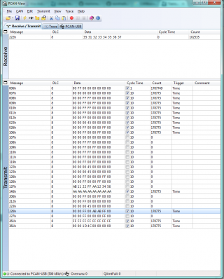
this is the pcan screenshot
Immagine1.png
 
You are not setting the message length when sending from the second Teensy, so (buf[0] == 49) will always be false.

I put the length on the second Teensy but still not working, because the program on the frist Teensy never passes the " if(myCAN.available()) " , for some reason myCAN.available() always return a 0. I checked the bus in a Osciloscope and theres data on it, but i can't make the comunication.
 
it may sound silly but when i can't initialize the bus normally the bus itself is not ok, missing terminators or pairs not twisted or ground levels too different, the other issue could be that the teensy can't initialize an empty bus therfore i would suggest to connect before another CAN hardware like a pcan dongle.
i'm using the flexcan with teensy and a pcan dongle and everything is ok.
Cheers.

I'll check it today to see what's what, but is really important to have twisted wires or pairs?
 
Twisted pairs i not that importan unless you work beside a nuclear fusion reactor :) or if you lines are gettin very long.
Just check wires ad termination resistors (1 on 20cm short wires at 500kbit/s is enough), by spec you need 2, by mistake i got a car canbus working fine with 3 resistors.
you line should be like:

Code:
+----CAN-H----+
|             |
R             R
|             |
+----CAN-L----+

If all is ok then you should have a look to the transcivers one may be dead.
 
Last edited:
i figured out why my filtering was not working, i forgot to set the mask, for who will need here is a working can filtering sketch.


Code:
// -------------------------------------------------------------
// CANtest for Teensy 3.1
// by teachop
//
// This test is talking to a single other echo-node on the bus.
// 6 frames are transmitted and rx frames are counted.
// Tx and rx are done in a way to force some driver buffering.
// Serial is used to print the ongoing status.
//

#include <Metro.h>
#include <FlexCAN.h>

Metro sysTimer = Metro(1);// milliseconds

int led = 13;
FlexCAN CANbus(500000);
static CAN_message_t msg,rxmsg;
static uint8_t hex[17] = "0123456789abcdef";

int txCount,rxCount;
unsigned int txTimer,rxTimer;
static CAN_filter_t myFilter_0, myFilter_1;
static CAN_filter_t myMask;


// -------------------------------------------------------------
static void hexDump(uint8_t dumpLen, uint8_t *bytePtr)
{
  uint8_t working;
  while( dumpLen-- ) {
    working = *bytePtr++;
    Serial.write( hex[ working>>4 ] );
    Serial.write( hex[ working&15 ] );
  }
  Serial.write('\r');
  Serial.write('\n');
}


// -------------------------------------------------------------
void setup(void)
{
  Serial.begin(115200);
  myMask.rtr=0;
  myMask.ext=0;
  myMask.id=0xfff;
  CANbus.begin(myMask);
  pinMode(led, OUTPUT);
  digitalWrite(led, 1);
  myFilter_0.id = 0x002;
  myFilter_0.ext = 0;
  myFilter_0.rtr = 0;
  myFilter_1.id = 0x004;
  myFilter_1.ext = 0;
  myFilter_1.rtr = 0;
  delay(10000);
  Serial.println(F("Hello Teensy 3.1 CAN Test."));
  CANbus.setFilter(myFilter_0,0);
  CANbus.setFilter(myFilter_0,1);
  CANbus.setFilter(myFilter_0,2);
  CANbus.setFilter(myFilter_0,3);
  CANbus.setFilter(myFilter_1,4);
  CANbus.setFilter(myFilter_1,5);
  CANbus.setFilter(myFilter_1,6);
  CANbus.setFilter(myFilter_1,7);
  sysTimer.reset();
}


// -------------------------------------------------------------
void loop(void)
{
  // service software timers based on Metro tick
  if ( sysTimer.check() ) {
    if ( txTimer ) {
      --txTimer;
    }
    if ( rxTimer ) {
      --rxTimer;
    }
  }

  // if not time-delayed, read CAN messages and print 1st byte
  if ( !rxTimer ) {
    while ( CANbus.read(rxmsg) ) {
      //hexDump( sizeof(rxmsg), (uint8_t *)&rxmsg );
      Serial.print(rxmsg.id,HEX);
      Serial.print(":");
      Serial.print(rxmsg.buf[0],HEX);
      Serial.print(":");
      Serial.print(rxmsg.buf[1],HEX);
      Serial.print(":");
      Serial.print(rxmsg.buf[2],HEX);
      Serial.print(":");
      Serial.print(rxmsg.buf[3],HEX);
      Serial.print(":");
      Serial.print(rxmsg.buf[4],HEX);
      Serial.print(":");
      Serial.print(rxmsg.buf[5],HEX);
      Serial.print(":");
      Serial.print(rxmsg.buf[6],HEX);
      Serial.print(":");
      Serial.println(rxmsg.buf[7],HEX);
      rxCount++;
    }
  }

  // insert a time delay between transmissions
  if ( !txTimer ) {
    // if frames were received, print the count
    if ( rxCount ) {
      Serial.write('=');
      Serial.print(rxCount);
      rxCount = 0;
    }
    txTimer = 100;//milliseconds
    msg.len = 8;
    msg.id = 0x222;
    for( int idx=0; idx<8; ++idx ) {
      msg.buf[idx] = '0'+idx;
    }
    // send 6 at a time to force tx buffering
    txCount = 6;
    digitalWrite(led, 1);
    Serial.println(".");
    while ( txCount-- ) {
      CANbus.write(msg);
      msg.buf[0]++;
    }
    digitalWrite(led, 0);
    // time delay to force some rx data queue use
    rxTimer = 3;//milliseconds
  }

}
 
Awesome work on this.

Using some of your notes on CANBus I am reading and writing to a medium speed can in a Ford vehicle and beginning to make a library of the body functions on that bus. I have one issue that I am hoping someone can help with. Much of the information broadcasting on that bus occurs at set intervals - typically every second. 2 in particular I would like to intercept and then write my preferred frame back. Because of the nature of that bus, it has thousands of frames on it in just a couple of seconds. I am successful at suppressing the message I want to block by flooding the bus, but I would much rather intercept it as it occurs using a switch.

My current sketch to intercept with a switch reads each incoming frame and looks for 2 can IDs. It can keep the native signal suppressed around 90% of the time, but the message being sent from the vehicle controller will get through for just long enough to flash on the indicator before being suppressed again - due to the FI FO nature of the bus I suspect. Is there a better method to intercept and block it - possibly by defining a priority so that the writing of the frame is not waiting on the bus to clear to transmit?

In order for my flood suppression to work (without using a switch to catch it), I have to pass my frame in at 5 times the rate as it normally occurs. I have concerns about keeping the bus flooded with that traffic.
 
Hi!
I'm sorry I don't have the answer to your question, but I was wondering if you'd be willing to share your code?
I have been having trouble writing with mine so I'm keen to see how others are doing it.
 
Would you not need to physically split the bus to prevent the original message making it to it's destination? Split the bus, pass everything through except the messages you want to modify (for these you'd read them and pass on a modified version). I tried doing something similar to what you are doing with RPM on my bikes dash. I sent my RPM signal just after the ECU sent one. It sort of worked but you could tell the dash wasn't happy recieving two differing messages at almost the same time. Look up 'canbus triple' this was a kickstarter that was intended to physically split the bus and modify selected messages.

Awesome work on this.

Using some of your notes on CANBus I am reading and writing to a medium speed can in a Ford vehicle and beginning to make a library of the body functions on that bus. I have one issue that I am hoping someone can help with. Much of the information broadcasting on that bus occurs at set intervals - typically every second. 2 in particular I would like to intercept and then write my preferred frame back. Because of the nature of that bus, it has thousands of frames on it in just a couple of seconds. I am successful at suppressing the message I want to block by flooding the bus, but I would much rather intercept it as it occurs using a switch.

My current sketch to intercept with a switch reads each incoming frame and looks for 2 can IDs. It can keep the native signal suppressed around 90% of the time, but the message being sent from the vehicle controller will get through for just long enough to flash on the indicator before being suppressed again - due to the FI FO nature of the bus I suspect. Is there a better method to intercept and block it - possibly by defining a priority so that the writing of the frame is not waiting on the bus to clear to transmit?

In order for my flood suppression to work (without using a switch to catch it), I have to pass my frame in at 5 times the rate as it normally occurs. I have concerns about keeping the bus flooded with that traffic.
 
Would you not need to physically split the bus to prevent the original message making it to it's destination? Split the bus, pass everything through except the messages you want to modify (for these you'd read them and pass on a modified version). I tried doing something similar to what you are doing with RPM on my bikes dash. I sent my RPM signal just after the ECU sent one. It sort of worked but you could tell the dash wasn't happy recieving two differing messages at almost the same time. Look up 'canbus triple' this was a kickstarter that was intended to physically split the bus and modify selected messages.

Splitting the bus will work, however it adds a layer of complexity and I would need to "double up" my teensy boards. One for reading and one for writing. I also would need to figure out how to "turn on" the bus on the particular component. It does not start listening or broadcasting until it sees the bus. It would be great if there was a way to sync the frames up. I may look for not trying to figure this out.
 
Hi!
I'm sorry I don't have the answer to your question, but I was wondering if you'd be willing to share your code?
I have been having trouble writing with mine so I'm keen to see how others are doing it.

Post your code up maybe we can help. I find the flexcan library fairly easy to use so let's see if we can find out how to get yours working.
 
Hey guys I finally made it, the communication works but I have just one issue. I'm using a Kvaser Leaf to test the CAN bus and I send messages through the Can BUS but sometimes the Teensy changes his ID, I don't know why and to find out what is it's ID I have to try one by one. How I can find out what's the Teensy ID or how can I define it?
 
Hey guys I finally made it, the communication works but I have just one issue. I'm using a Kvaser Leaf to test the CAN bus and I send messages through the Can BUS but sometimes the Teensy changes his ID, I don't know why and to find out what is it's ID I have to try one by one. How I can find out what's the Teensy ID or how can I define it?

What ID are you talking about? I did notice a hardware ID when using the duecan library that would change, but it was irrelevant to sending/receiving data. You can define the frame ID for every message sent.
 
Hey all!
I'm having issues sending as well (saw Foyds problems). From my analysis of the TRM of CAN and reviewing the driver it seems as if the message buffers aren't being emptied (TX process isn't starting due to arbitration nothing working). I added some debug messages to the driver to figure out what's going on:

Code:
This is UART Log Task 54

.
starting can tx
found buffer
sending message
starting can tx
found buffer
sending message
starting can tx
no buffers :(
starting can tx
no buffers :(
starting can tx
no buffers :(
starting can tx
no buffers :(
This is UART Log Task 60

.
starting can tx
no buffers :(
starting can tx
no buffers :(
starting can tx
no buffers :(
starting can tx
no buffers :(
starting can tx
no buffers :(

I didn't have it hooked up to a transceiver (TxR) first just to see if it was sending bits, it wasn't so I figured the arbitration wasn't starting due to missing TxR. I've designed CAN communications systems before but never wrote the software for it but I have knowledge of uC intereworkings.

I've attempted this with just the example and I've tried it with some modifications and using FreeRTOS implementation. It gets into the driver, the driver setups the message buffer but the hardware never sends.

Code:
//Teensy 3.1 FreeRTOS
#define TEENSY_FREERTOS
#include "FreeRTOS.h"
#include "task.h"
#include "timers.h"
#include <FlexCAN.h>
#include <kinetis_flexcan.h>

#define mainQUEUE_RECEIVE_TASK_PRIORITY    ( tskIDLE_PRIORITY + 2 )
#define UARTLog_Task_Priority       ( tskIDLE_PRIORITY + 2 )
#define mainLED_TIMER_PERIOD_MS   ( 3000UL / portTICK_RATE_MS )
#define mainDONT_BLOCK  (0)
// set this to the hardware serial port you wish to use
#define HWSERIAL Serial1

#define mainCAN_COUNTER_TX_ID				0x200

static xTimerHandle xLEDTimer = NULL;
FlexCAN CANbus(125000);
static CAN_message_t msg;


//
//static void prvQueueReceiveTask(void *pvParameters)
//{
//  while(1)
//    {
//        digitalWriteFast(13, HIGH);
//        //delay(10);
//        vTaskDelay(1000);
//        digitalWriteFast(13, LOW);
//        //delay(1000);
//        vTaskDelay(1000);
//    }
//}

static void UARTLogTask(void *pvParameters)
{
  int count = 0;
  int txCount = 0;
  while(1)
    {
      Serial.print("This is UART Log Task ");
      Serial.println(msg.buf[0], DEC);
      Serial.print("\n");  
      HWSERIAL.print("This is UART Log Task ");
      HWSERIAL.println(count, DEC);
      HWSERIAL.print("\n");
      count++;
      
      //CAN MESSAGE 
      msg.len = 8;
      msg.id = mainCAN_COUNTER_TX_ID;
      txCount = 6;
      digitalWriteFast(13, HIGH);
      Serial.println(".");
      while ( txCount-- ) {
        CANbus.write(msg);
        msg.buf[0]++;
      }
      digitalWriteFast(13, LOW);
      //digitalWriteFast(13, LOW);
      
      
      //delay(200);
      vTaskDelay(5000);
    }

}

static void prvLEDTimerCallback( xTimerHandle xTimer )
{
  static int toggle = 0;

  if(toggle == 0) {
    digitalWriteFast(12, HIGH);
    toggle = 1;
  }
  else {
    digitalWriteFast(12, LOW);
    toggle = 0;
  }


}

void setup() {
  // put your setup code here, to run once:
  pinMode(13, OUTPUT);
  pinMode(12, OUTPUT);
  Serial.begin(38400);
  HWSERIAL.begin(38400);
  CANbus.begin();
  for( int idx=0; idx<8; ++idx ) {
    msg.buf[idx] = '0'+idx;
  }

  //xTaskCreate( prvQueueReceiveTask, "Rx", configMINIMAL_STACK_SIZE, NULL, mainQUEUE_RECEIVE_TASK_PRIORITY, NULL );
  xTaskCreate( UARTLogTask, "ULog", configMINIMAL_STACK_SIZE, NULL, UARTLog_Task_Priority, NULL );

  xLEDTimer = xTimerCreate(   "LEDTimer",           /* A text name, purely to help debugging. */
                ( mainLED_TIMER_PERIOD_MS ),  /* The timer period, in this case 5000ms (5s). */
                pdTRUE,           /* This is a one shot timer, so xAutoReload is set to pdFALSE. */
                ( void * ) 0,         /* The ID is not used, so can be set to anything. */
                prvLEDTimerCallback       /* The callback function that switches the LED off. */
                );
                
  Serial.print("End of Setup\n");
  HWSERIAL.print("End of Setup\n");

}

void loop() {
  // put your main code here, to run repeatedly:
   Serial.print("MainLoop Start\n");
   HWSERIAL.print("MainLoop Start\n");
   xTimerStart( xLEDTimer, mainDONT_BLOCK );
   vTaskStartScheduler();
}

Any thoughts would be greatly appreciated!
 
To have a functionibg CAN bus, you do need at least two nodes ... the transmitter needs an Ack from the receivers. It is not clear to me thst you have that. Some examples use loop back or two channels to avhieve that.
 
I have a CAN analyser but no I don't have anything to ACK but the modules has to SEND something for me it ACK. I also have a logic analyser on the pins and NOTHING comes out of them. I would expect some sort of BUS activity. I do notice that Freeze ACK is always on and I cannot get it to turn off and all my buffers are stuck in CODE = 0xC.
 
Finally made it, it was the filters that I havent defined it on my code so the teensy assigned them some stuff.
 
Hi;
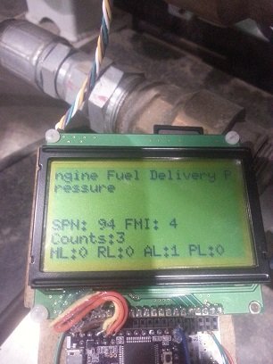
Just want to add something for anyone else interested in j1939. Teachop's Flex can works well for the extended ID and j1939. I have a very rough code reader that has been tested on some industrial engines, QSK 50, QSK 45, and some smaller tractor engines too. Once the code is in a less embarrassing state I will post it.

WP_20151019_001.jpg
 
here is a snippet of code for anyone trying to decode j1939 error codes with the flexcan library:

Code:
sourceAddress = rxmsg.id & 0x000000ff; // mask out 2 byte source address
PGN = (messageID & 0x3FFFF00) >> 8 ; // mask out 19 bit PGN and shift

  if (PGN == 65226) // PGN for active codes
  {
//________________________SPN
  SPN = (data5 & B11100000) << 16; // clear first 5 bits && move to correct MSB
  SPN =  SPN + (data4 << 8);    // add second byte and move to correct position
  SPN = SPN  + data3;         // add third byte LSB
  //________________________Fault Mode Indicator
  FMI = data5 & B00011111; // clear first 5 bits
  //________________________occurance count
  OC = data6 & B01111111; // clear first 5 bits
  //________________________malfunction lamp
  malfunctionLamp = (data1 & B11000000) >> 6; // use bits 1-2
  //________________________red stop lamp
  redLamp = (data1 & B00110000)  >> 4; // use bits 3-4
  //________________________amber warning lamp
  yelLamp = (data1 & B00001100) >> 2; // use bits 5-6
  //________________________protect lamp
  protectLamp = data1 & B00000011; // use bits 7-8
}
 
Hello.

I have a small project that I am working on, that is using the FlexCAN Library. All is working great! Thanks to all those that have contributed.
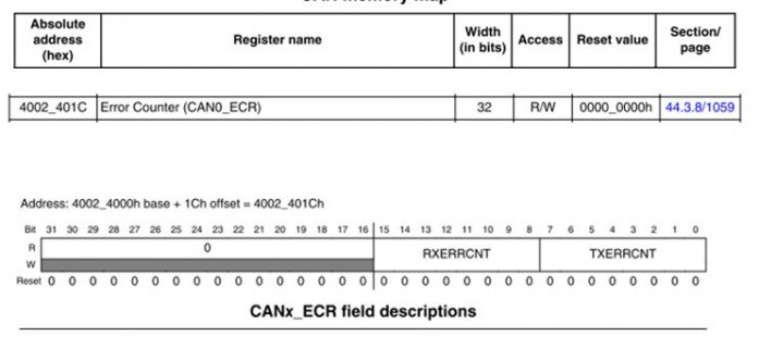
For the purpose of background checking I would like my code to periodically read the CAN ‘TX & RX’ Error Counter registers that I can see listed in the Freescale Reference Manual.
I may only use these values during development, but having access to them during run-time would be great for picking out bad hardware etc

From the Freescale Reference Manual pages 1046 and 1060 (as per the image below)
The Register Error Counter (CAN0_ECR) contains 2 x 8 bit counters that reflect the Transmit and Receive Error counters.

Capture.JPG

I can see that the FlexCAN Library has provision for this register; specifically it is listed in the file (kinetis_flexcan.h) as follows:

#define FLEXCAN0_ECR (*(vuint32_t*)(FLEXCAN0_BASE+0x1C))

Using the FlexCAN Library, this register decodes to the 0x4002401C address.
The library also lists a second Error counter:

#define FLEXCAN1_ECR (*(vuint32_t*)(FLEXCAN1_BASE+0x1C))

Using the FlexCAN Library, The FLEXCAN1_ECR register decodes to the address 0x400A401C, but I am not sure if this is an error in the library as this register does not appear to exist in the Freescale Document? I could be overlooking something here though.

I have been attempting to extract the value of the above registers to use in my code, but with no success. Being honest I have hit knowledge/my coding skills wall.

Q) Does anyone know a way (or have a close example that I could follow) of how I could directly read an internal Register from the Teensy to use in my code?

Thanks guys!
Keith
 
Last edited:
I gave this a go, it appears to increase in number with an error condition. Though I guess to truely introduce single CAN errors I would need a method to control a glitch onto the lines.


What I tried, In the header::

#define CAN_ERROR_COUNTERS 0x4002401C // Register for the CAN ERROR COUNTERS
unsigned int volatile *const port = (unsigned int *) CAN_ERROR_COUNTERS;
unsigned int value;


Then in the main code ::

value = *port; // Reading the Number of CANbus Errors
Serial.print("CANBUS Errors ::"); // Diagnostic Terminal Feedback
Serial.println(value,DEC); // Diagnostic Terminal Feedback

The value reported starts out at 0 and as I introduce hard errors (simulated by removing and re-making the RX pin wire from the CAN Transceiver into the Teensy) it rapidily increases.
I need to read the documentation over more thoroughly as counter resets back 0 after a period of the link operating cleanly (this might well be the expected behaviour though).
I know that I am not breaking this down into RX / TX errors at this stage, it is just a starting point.

Thanks
 
Hello,

i want to switch from my arduino with can bus shield to teensy 3.1 / 3.2 with can bus.
As i now know is, i need a mcp2551. I can use the one from one of my can-shields i allready have.

Now my questions:
Which library should i use?
FlexCan, is that right? I had a look at the example and it looks like it is more complicated than the arduino can library.
Is there an example with mask and filter for receive messages?

Is there any Feedback for the Can begin?

How do i connect the MCP2551?
Here what i think:
MCP2551 | Teensy
1 TXD | 3 TX
4 RXD | 4 RX
3 VDD 5V | Teensy 5V
2 VSS | Teensy GND

And Can_L and Can_H for my communication.
Do i need any other things? I don't need a end-resistor i just want to sniff for the beginning.

I hope it will be easy like i think :)

Thank you

Regards
Thomas
 
1 TXD | 4 RX
4 RXD | 3 TX

Also, make sure your MCP2551 has common ground to the object (car, motorcycle) you're reading from. Just CAN L+H isn't usually enough.
The example in flexcan is enough to read all data going around the bus, but you need to make sure you set the correct baud rate in the example (usually 500Kbit).
 
Last edited:
Oh RX <-> TX, on page 4 there was a post that in this case it has to be TX <-> TX because of some specs.
That was something i was wondering, but now it is clear, RX<->TX makes more sense :)

Common ground i will have later, but my tests with arduino and laptop as power-supply do not have the same ground, but it is working.
I think same should be with teensy. But i will see with my tests.

So everything i need to do is connect the MCP2551 to the teensy? Because i found some circuits where a capacitor was used.

Anyway, i will test asap.

Thanks a lot.
 
Sorry for misleading, it really is Tx-Tx/Rx-Rx due to the very confusing pin descriptions on the MCP.

In my tests I used the MCP without the capacitor and it worked fine.
 
Back
Top