Power from both USB and external

Status
Not open for further replies.

nlecaude

Well-known member
Hello,

I have a project where I would like to power the teensy from usb when plugged into a computer but also have an optional external power when it is connected to an iPad.
Would a DC connector with integrated switch work for this ?
I would cut apart vin and vusb. The (normally closed) switch of the dc connector would be soldered to vin and vusb meaning that when no plugs are in vin and vusb are connected. If I insert power in the dc barrel then vusb gets disconnected and ground and vin get power from the external supply.
Does that seem to make sense ?
 
Sounds like it should work. You might want to check that the contacts and "break before make", but I believe pretty much all of those types of connectors are.
 
Another option is using a Schottky diode per input to allow one or both devices to be plugged in at once, providing power as needed. Just keep a common ground and all should be well.

The reason to use a Schottky vs a regular diode is the lower voltage drop across the diode. That in turn helps the voltage regulator maintain a nice stable voltage.

In my design I have Vusb going into one Schottky and a on-board switchmode power supply going into another. Whichever supply features a higher voltage then supplies the voltage regulator supplying the board with power.

You have to cut the Vin-Vusb connector for this particular approach to work and I have focused on doing it this way to use a external voltage regulator instead of the on-board unit inside the k20 chip. I want my k20 to run as cool as possible.

However, your approach sounds like a really good one. I like how it uses a simple mechanical system to achieve the same goal as the diode approach.
 
Thanks for the tips ! I'll try the mechanical way and report back. I'll try the diode way if I have issues. The only downside I see is that the switch is on the barrel side meaning I have to use the barrel for vin and the pin for ground which I always find counterintuitive.
 
Is there some other way not to avoid cutting traces? The only other way I can think of is to mod the USB cable and cut VBUS..
 
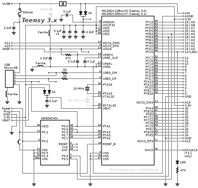
Have a look at the schematic for the Teensy 3 and 3.1

Is there some other way not to avoid cutting traces? The only other way I can think of is to mod the USB cable and cut VBUS..

schematic3.gif


Note the VUSB and VIN connection up top.

I wonder if there is a potential improvement opportunity if one were to connect the two pads that connect the VIN-USB signal individually to the legs of the SOT23 Schottky diode that feeds the voltage regulator. That way, either VIN or VUSB could feed the voltage regulator inside the K20 chip if the connection were cut. Hence, dual power supplies would be somewhat easier to implement. However, it's very likely that Paul considered this option and discarded it for very good reasons that we are not privy to.

So, in the meantime, I simply use two external Schottky diodes to switch between VUSB and an external 5VDC power supply for the MCP1825 voltage regulator I use to power the K20 chip. The K20 internal voltage regulator is currently unused. One option I have considered is powering the K20 solely with its internal voltage regulator while powering all other external devices with a external voltage regulator.

In theory, this could lead to better performance since it would give the external power supply even more headroom margin. I haven't elected to do this because it would lead to more heat generation inside the K20, which could interfere with ADC operations via thermal drift. But if only the K20 chip is powered by the internal voltage regulator, it may represent such a small load as to be inconsequential from a thermal point of view.
 
Yeah, I've wanted to have a USB cable that has a female connection on one side (probably micro these days) and an appropriate male connection on the other side with a 5v/ground cable coming off that would allow access to the 5v power before plugging it into the micro processor (the 5v side cable would have a diode on it to prevent power going back to the host). I imagine it is easy enough to create such a franken-cable, but I don't know what kinds of protection needs to be added. This would primarily be for things like powering a few WS2812 lights with a single connection, and not having to worry about overloading the VIN pin.

At other times, I want a cable with a USB input, secondary power (regulated 5v), and USB output. If the secondary power is on, it would use that instead of the USB power. I'm not sure however, whether it would prevent USB communication to/from the host if power isn't drawn from the USB cable.

Sooner or later, I imagine it will motivate me to learn the electronics side of things (as compared to the programming side).
 
Last edited:
while cutting traces, couldn't one put in a pair of Schottky diodes to wire-or the two sources of 5VDC?
 
while cutting traces, couldn't one put in a pair of Schottky diodes to wire-or the two sources of 5VDC?

Good point, there is a large pad that is dedicated to VIN and VUSB, respectively, so it would be relatively trivial to cut the trace and then solder a SOD123 1A Schottky diode to allow power to only run from VUSB to VIN. Even with a dual Schottky voltage drop (i.e. the Schottky you added, plus the one already on the board), I'd expect the on-chip voltage regulator to be OK. After all, the average voltage drop across a Schottky is less than 0.3V, so the total voltage drop is less than 0.6VDC.
 
Michael, I'd consider buying a USB isolator from Oleg instead. All the options you mentioned, plus the ability to optically isolate your CPU, if needed.
Originally, I thought that is what I'm looking for, but doesn't quite do what I want.

My current interests are for battery powered neopixel (ws2812) setups for costumes. While I'm writing the software, I need the USB interface, but ideally I want to do the testing with the actual power source I'm going to use without having to do the download and then unplug the board to do the testing. I worry that the PC's USB side won't be able to supply the power for the neopixels (so far, with 2 rings and the light fairly low, it seems ok, but I may have been just lucky).

Oleg's device has two problems: 1) the external power needs at least 7v, which limits my battery choices; and more importantly to the project 2) the isolator will only deliver 600maH of power. What I would like is something that can take 3.7v - 7.4v (i.e. 1s/2s lipo batteries, 4-8 AA battery packs, or USB rechargers up to 1aH) and deliver 5v 1a (or more) of power. I don't want 2 power sources to cut down on weight and to improve reliability.
 
Last edited:
FYI, Found this board http://www.pololu.com/product/2594 the draw back is wiring the USB from the board to the teensy. This way no traces have to be cut.

What a great part/solution. Thanks for finding and posting it. This is a great solution for applications where voltage drop on multiple input sources is not acceptable and hence even schottky diodes are out of the question. Pity though that the chip at the heart of that breakout board is only available as a BGA. That really makes life interesting for anyone other than professionals to mount the thing.
 
FYI, Found this board http://www.pololu.com/product/2594 the draw back is wiring the USB from the board to the teensy. This way no traces have to be cut.

That looks great! Thanks. I was just about to wire up a similar solution (but using a physical switch instead of automatic switching to avoid the voltage drops). I might put a step-up/step-down converter like this: http://www.pololu.com/product/2123 on the power output, just to be sure I get 5v, no matter what the secondary battery is running at.
 
Last edited:
FWIW, I typically use a simple 3-pin 0.1" pin header and a single jumper shunt to switch back and forth manually between power sources when the voltage has to be preserved (i.e. when even Schottky diodes introduce unacceptable voltage drop). The center pin is the the one that the shunt shorts to. That way, there is no way for two power sources to be enabled on the same circuit. Extending the concept, use a 4-pin "T"-shaped configuration to switch among three external power sources, or a 5-pin "+" shaped array to sample among 4 power sources.

Neither configuration is as convenient as the 3-pin header from an assembly point of view because it's harder to solder 1 or two individual pins. But doable and a lot less expensive than these (admittedly cool and elegant) solid state switching solutions from Fairchild/Pololu.
 
Last edited:
That looks great! Thanks. I was just about to wire up a similar solution (but using a physical switch instead of automatic switching to avoid the voltage drops). I might put a step-up/step-down converter like this: http://www.pololu.com/product/2123 on the power output, just to be sure I get 5v, no matter what the secondary battery is running at.
Beware those step-up/down conveters: The one mentioned seems to lack a specification on output current where the voltages for input = output. It is not 1A as spec'd as best case (that might happen with 11V in).
I doubt it'll provide 500mA at 5V with 4.7 in. Probably more like 100mA.
But I didn't see it spec'd.
 
Just scroll down the page and there is a chart that explains what output current over input voltage can be expected across the whole input voltage range :roll eyes:
Generally the Pololu stuff is very well designed.
 
Thanks. Oops.. I did look for the chart but didn't see it.

I bought recently a step-up converter... 12V out. Its output current was no where near what was claimed it could do.
 
Status
Not open for further replies.
Back
Top