Audio Library

Status
Not open for further replies.
I am using Teensy 3.1, teensy loader1.20, and 1.02 Audiolibrary version.
Here is code with just four sine osc, three fade objects and one osc without fade. It doesnot work, even serial communication is not working.
Please do you have any idea what is wrong?

I can't tell from only a quick look.

Could you give File > Examples > Audio > Synthesis > PlaySynthMusic a try? It uses 16 waveform generators and 16 envelope effects.

Also, please try with Arduino 1.6.3 or 1.6.5 with the latest Teensyduino 1.25 (and the copy of the Audio library it provides.... watch for any messages about duplicate copies of libraries). If this is a bug in the older copy of library you have, upgrading might magically make things work. Even if it doesn't fix things, it's helpful if we're both testing on the very latest version!

If that example doesn't help, let me know and I'll try to look deeper into this.
 
About my problem with fade object. I've tried all recomended things but with now succes:
- new arduino IDE 1.6.3 ( I am still on Snow Leopard so the newest 1.6.5 is only for Lion ++),
- new Teensyduino,
- AudioLibrary that I use is the newest stable
I tried the Playsymthmusic and it works. ( I had to change output routing for dac1 that I am using but its just formality).

I tried also to put out all serial communication that I am sending to another teensy which is controlling 12 RGB leds with TLC drivers. No improvement.
I tried also to use FMsine instead of simple sine osc and it does not work even without fade object. So there is maybe something more complex than just issue with fade object.
I tried to change memory size to 18, 32 and it made just buzzy sound and freeze.

-
This warning was in arduino ide during compiling:
MONOLIT_audio_jdekomunikace_EXPAND_AAA.ino: In function 'void loop()':
MONOLIT_audio_jdekomunikace_EXPAND_AAA.ino:149:16: warning: iteration 11u invokes undefined behavior [-Waggressive-loop-optimizations]
MONOLIT_audio_jdekomunikace_EXPAND_AAA.ino:148:3: note: containing loop

But this warning is also in working version of code without fades....

Please do you have any idea what can be wrong?
Thanks a lot!
Jiri
 
Hi everyone. Just got Teensy 3.1 with the audio adapter to do simple baseband processing (Hilbert xform for SSB) for my DSP radio project. Have few questions:
1. I need to subtract two audio streams. Can I use negative gain parameter in the mixer block for that ? What are the alternatives ?
[edit]Checked the mixer source code, as is, the gain is positive only but seems easy to modify. Modified the header file, seems OK[end edit]

2. Are coefficients for the library FIR filter in Q.15 format ?
[edit]Looking at the source code looks like it is. But having trouble with odd number of taps for now... Aha, figured it out, the underlying CMSIS lib does not support odd number of taps, needs to be padded to even.[end edit]

3. Is it possible to slow down the codec sample rate to 22kHz or 16kHz somehow ?
[edit]Ok, I found the example in post #573 how to set the codec to master mode and modified CHIP_CLK_CTRL for 16kHz. I got the proper clocks (when the board is set to the 96MHz). However there is an initialization issue: it only works if I reconnect USB (power reset the codec)[end edit]
[edit2]Still no idea why the codec does not like to be initialized after it's PLL has been enabled :( However I've added a really crude workaround - after I2S0_* writes I read the CHIP_ANA_POWER register and if PLL is already turned on I skip the rest of the routine. At least it makes rebuild-check faster, no need to unplug the USB cable[end edit2]

Thanks in advance.
 
Last edited:
Hello Paul,

first of all, thank you for your GREAT job! I am using teensy (2++ and 3.1) in differents applications, and it works great.

Concerning the audio library, there is one feature that has already been discussed, and also a great work has been done by MickMad here

the USB audio interface!

At this stage is it usable? could we use the teensy 3.x as a soundcard? that would be great..

I have been considering using TI's PCM291x wich are easy to use, but quite limited.
I would definitively prefer to use the Teensy as an audio interface...

Thank you!
 
Hi Anthony,

I don't know where USB audio is on Paul's list, but I'm looking into furthering the work done by MickMad to try to get USB audio working with my SuperAudioBoard project (see the forum thread or the hackaday project page).

I've got MickMad's changes integrated into the current version of Paul's core library (some of the USB code has changed a little, so I had to merge the changes back in), but I haven't had a chance to test it yet. I also need to do some research to see what USB audio modes will work with the codec driving the I2S clocks.

The end goal would be to get the USB audio stuff integrated into the audio library, but that may be a while yet.
 
Hi,

I have a project with the teensy 3.2, the audio adaptor, a micro SD card (8GB sanDisk Ultra), an amplifier (sure electronics 2X25W TDA7492) and surface exciters. It's running outside day and night in a sealed box in Canada, and we want to keep it running for a year. We had problems recently with some of the units doing a constant loud frequency. We think it might be the teensy since the problem stops after unplugging and plugging the total Unit. It's a project with limit details here, but my question is more code-wise.

I took the Sdcard example and changed it a little bit and i was wondering if those changes might have troubled the microcontroller in a not so frequent instability? The code is only reading one file of about 1min30 in loop forever (which has the same name of the .wav example, but it is a different file). We have 6 units and 3 of them have now the same bug, one after one day, the second after 2 weeks, and the other after a month.

Can anyone can see a problem with this code, or a source for that unwanted frequency? Is the delay(5) is sufficient at the call of the playFile function to keep the microcontroller stable? Just to mention I got rid of the delay(500) to have a nice constant loop. The access to the units is for the moment complicated, so it's hard to troubleshoot only by unplugging/plugging the box. Thanks for your help!!


Code:
// Source: [url]http://platformio.org/#!/lib/show/70/Audio?example=WavFilePlayer.ino[/url]
// ******IMPORTANT********: Only 16 bit PCM, 44100 Hz WAV
//simple WAV file player example
//
// Three types of output may be used, by configuring the code below.
//
//   1: Digital I2S - Normally used with the audio shield:
//         [url]http://www.pjrc.com/store/teensy3_audio.html[/url]
//
//   2: Digital S/PDIF - Connect pin 22 to a S/PDIF transmitter
//         [url]https://www.oshpark.com/shared_projects/KcDBKHta[/url]
//
//   3: Analog DAC - Connect the DAC pin to an amplified speaker
//         [url]http://www.pjrc.com/teensy/gui/?info=AudioOutputAnalog[/url]
//
// To configure the output type, first uncomment one of the three
// output objects.  If not using the audio shield, comment out
// the sgtl5000_1 lines in setup(), so it does not wait forever
// trying to configure the SGTL5000 codec chip.
//
// The SD card may connect to different pins, depending on the
// hardware you are using.  Uncomment or configure the SD card
// pins to match your hardware.
//
// Data files to put on your SD card can be downloaded here:
//   [url]http://www.pjrc.com/teensy/td_libs_AudioDataFiles.html[/url]
//
// This example code is in the public domain.
#include <Audio.h>
#include <Wire.h>
#include <SPI.h>
#include <SD.h>
#include <SerialFlash.h>

AudioPlaySdWav           playWav1;
// Use one of these 3 output types: Digital I2S, Digital S/PDIF, or Analog DAC
AudioOutputI2S           audioOutput;
//AudioOutputSPDIF       audioOutput;
//AudioOutputAnalog      audioOutput;
AudioConnection          patchCord1(playWav1, 0, audioOutput, 0);
AudioConnection          patchCord2(playWav1, 1, audioOutput, 1);
AudioControlSGTL5000     sgtl5000_1;

// Use these with the audio adaptor board
#define SDCARD_CS_PIN    10
#define SDCARD_MOSI_PIN  7
#define SDCARD_SCK_PIN   14

// Use these for the SD+Wiz820 or other adaptors
//#define SDCARD_CS_PIN    4
//#define SDCARD_MOSI_PIN  11
//#define SDCARD_SCK_PIN   13

void setup() {
  Serial.begin(9600);

  // Audio connections require memory to work.  For more
    // detailed information, see the MemoryAndCpuUsage example
  AudioMemory(8);

  // Comment these out if not using the audio adaptor board.
  // This may wait forever if the SDA & SCL pins lack
  // pullup resistors
  sgtl5000_1.enable();
  sgtl5000_1.volume(0.675); // 0 (muted) to 0.99, If over, it will mute the volume. 
  sgtl5000_1.volume(0.725, 0.675); // volume(left, right) Must call the volume(arg) first to work

  SPI.setMOSI(SDCARD_MOSI_PIN);
  SPI.setSCK(SDCARD_SCK_PIN);
  if (!(SD.begin(SDCARD_CS_PIN))) {
    // stop here, but print a message repetitively
    while (1) {
      Serial.println("Unable to access the SD card");
      delay(500);
    }
  }
}

void playFile(const char *filename)
{
  Serial.print("Playing file: ");
  Serial.println(filename);

  // Start playing the file.  This sketch continues to
  // run while the file plays.
  playWav1.play(filename);

  // A brief delay for the library read WAV info
  delay(5);

  // Simply wait for the file to finish playing.
  while (playWav1.isPlaying()) {
    // uncomment these lines if you audio shield
    // has the optional volume pot soldered
    //float vol = analogRead(15);
    //vol = vol / 1024;
    // sgtl5000_1.volume(vol);
  }
}


void loop() {
  playFile("SDTEST1.WAV");
}
 
That could be a problem with the contacts of the SD slots or card.
Have you thought of using the optional SPI flash chip?
 
Hi Paul,

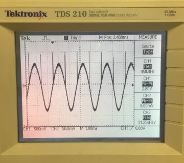
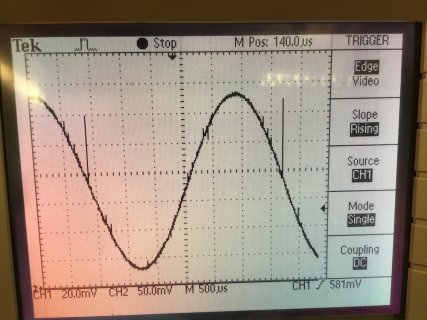
I'm using the Audio Library on a Teensy 3.1. It works well, but as you can see in the attached image I get spikes on the zero crossings when I generate sine waves.

sinespikes.jpg

My guess is that you're using a 1/2 wave buffer to generate the sines (flipping the sign to generate the 2nd half of the waveform) but that you have an off by one error at the end of the buffer that's causing the spikes. The spikes are always on the zero crossings, regardless of the frequency of the sine wave, which is why I think it's a problem with the buffer reading code. Can you take a look when you get a chance?

I'm surprised no one has mentioned this (I've searched the forum), but maybe mostly people are playing back samples?


best,
douglas
 
Hmmm, I found this:

https://github.com/PaulStoffregen/Audio/blob/master/data_waveforms.c

and it looks like you're using a full wave LUT. So if there's an off by one error I'd think it would only show up at the end of each full cycle. But the scope clearly shows that there's a spike at each zero crossing. That's really strange. I'll keep poking around.

FWIW, I'm just creating an AudioSynthWaveformSine, hooking it to an AudioMixer4, then sending it to the 12bit DAC via AudioOutputAnalog.


best,
douglas
 
FWIW, I'm just creating an AudioSynthWaveformSine, hooking it to an AudioMixer4, then sending it to the 12bit DAC via AudioOutputAnalog.

No matter how simple, you must post the complete program to reproduce the problem if you want me or anyone else to actually look at this. Merely describing your program is not enough (eg, the "Forum Rule").
 
No matter how simple, you must post the complete program to reproduce the problem if you want me or anyone else to actually look at this. Merely describing your program is not enough (eg, the "Forum Rule").

Right, sorry, that's a great rule. Code and new pics below.

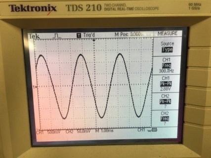
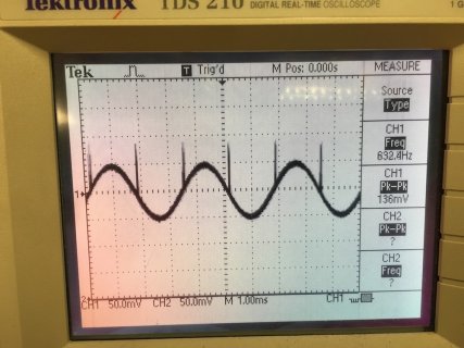
The first pic is a sine wave with an amplitude of 0.5. It looks fine. The 2nd is a sine wave with an amplitude of 0.01. It has crazy devil ear spikes. Both of these are running through an LA4425A amp chip. The third pic is a sine wave with an amplitude of 0.1 coming directly off of the DAC. It also has spikes. So I think there's something strange happening in the amplitude scaling code. High amplitude sine waves look fine, low amplitude waves have spikes. This becomes more pronounced if I run the signal through a mixer. If I set the mixer amplitude low, spikes are introduced. Let me know if you'd like me to do any tests.


best,
douglas


+++++++


#include <Audio.h>
#include <Wire.h>
#include <SPI.h>
#include <SD.h>

/* sine wave spike demo code */

AudioSynthWaveformSine sine1;
AudioOutputAnalog dac1;


AudioConnection patchCord1(sine1, dac1);

void setup()
{
AudioMemory(7);

sine1.frequency(300.0);

//change this to make spikes appear/disappear. 0.5 gives no spikes. 0.01 gives large spikes.
sine1.amplitude(0.1);
}


void loop()
{

}
 
sine_DAC_spikes.jpegsine_no_spikes.jpgsine_spikes.jpg

Sorry, on upload the order turned out to be:

0.1 amplitude direct from DAC
0.5 amplitude via amp chip
0.01 amplitude via amp chip
 
Last edited:
[edit]Checked the mixer source code, as is, the gain is positive only but seems easy to modify. Modified the header file, seems OK[end edit]
.

Hi vladn,
Can you share what you did with the mixer header file to do this subtraction of two audio signals?
Appreciate any code snippets,
Thank you
nhk
 
Hello and Happy Holidays to everyone! This community is amazing. I am an undergraduate researcher at U-Iowa and have been lurking for some time now trying to get the information to perform FFT on the teensy 3.1 using a MAX4466 with the output feeding directly to the on-board ADC without using the audio shield. I know people in this thread have talked about using the on-board ADC, but I can not figure out how to implement this into the FFT example code. I am simply trying to perform fft using 44.1kHz sampling rate. The project is to make an affordable network of sound level monitoring devices to record a-weighted noise levels in a factory setting and when I am setting up 5 or more devices, every dollar will count :/.

PS I apologize if the answer to this question is obvious and has been answered, but I am completely stuck and have been searching for a long time before asking.
Thanks!
 
Note, you meant DAC (digital to analog converter, i.e. pin A14 in the 3.1/3.2 or A12 in the LC), which outputs an analog signal. An ADC (analog to digital converter) is used when reading in analog inputs.
 
First, watch the tutorial video if you haven't already. The important parts are using the design tool, starting at 6:59 (perhaps watch 2 or 3 of those parts), and the FFT starting at 34:56.

As you can see in the video, the design tool lets you build an audio system. You don't have to use the I2S inputs/outputs. There's a ADC input which lets you get audio from the on-chip ADC instead of using the audio shield. You can build audio systems pretty much any way you want. Currently the library has only one non-I2S input object, so that's the only way to get a signal in without the audio shield.

A key point in the video is how you also use the design tool to discover the many audio capabilities and documentation about how to use each one. When you click on the ADC object in the design tool, you'll see the right-side panel updates with info about how to use it. Because it's just a normal analog pin on the microcontroller, you need a simple circuit to couple of the AC audio signal to the proper DC offset. The documentation recommends a circuit with 4 resistors and 2 capacitors.

It's really that simple. Just follow the FFT stuff from the video, but instead of the I2S object, put the ADC object onto your canvas. Delete the SGTL5000 object, since you won't have the audio shield, and delete the few lines from File > Examples > Audio > Tutorial > Part_3_02_Fourier_Transform that control the audio shield using that object.
 
Hi vladn,
Can you share what you did with the mixer header file to do this subtraction of two audio signals?
Appreciate any code snippets,
Thank you
nhk

Hey nhk, I have an old pull request in on Paul's work on github that does that, you might be able to find it, might even be able to egg Paul into accepting it although it would probably be a bigger pita to him now that it has aged somewhat.

I made an object for noise canceling purpose that may suit your requirement well enough: https://forum.pjrc.com/threads/28699-Little-audio-project?p=74097&viewfull=1#post74097
 
Hi Paul. Thank you very much! This is exactly what I am trying to do. I had not previously seen the video, but and watching it now that I have time. I will get a chance to set everything up tomorrow and will get back with an update.
Much appreciated.
 
I've been working on incorporating the teensy audio board into my R2-D2. Unfortunately all the sounds are in 22050Hz, 8-bit mono format. As such, the library won't play them. Having said that, I think I've got a fix, and wanted to see what people thought. The following code is added in to play_sd_wav.cpp in the consume function.

Code:
case STATE_CONVERT_8BIT_MONO :
    //TODO: Figure Out How To Convert
    if (size > data_length) size = data_length;
    data_length -= size;
    while (1) {
        lsb = *p++;
        //msb = *p++;
        //size -= 2;
        size -= 1;
        block_left->data[block_offset++] = (lsb << 7) | 0; // shift by 7 because 8 makes it noisy due to the 16-bit value being signed and the 8-bit being unsigned
        block_left->data[block_offset++] = (lsb << 7) | 0; // and just duplicate the value since it's 22050 Hz instead of 44100 Hz
        if (block_offset >= AUDIO_BLOCK_SAMPLES) {
            transmit(block_left, 0);
            transmit(block_left, 1);
            release(block_left);
            block_left = NULL;
            data_length += size;
            buffer_offset = p - buffer;
            if (block_right) release(block_right);
            if (data_length == 0) state = STATE_STOP;
            return true;
        }
        if (size == 0) {
            if (data_length == 0) break;
            return false;
        }
    }
    Serial.println("end of file reached");
    // end of file reached
    if (block_offset > 0) {
        // TODO: fill remainder of last block with zero and transmit
    }
    state = STATE_STOP;

    return false;

I realize that this is hard coded for the 22050Hz rate. Other than that, does it seem like a reasonable approach?
 
@dis
Code:
        block_left->data[block_offset++] = (lsb << 7) | 0;
I don't think this is correct. It will generate a signal with a DC offset.
Try:
Code:
        block_left->data[block_offset++] = (lsb - 128) << 8;
This converts the 8-bit unsigned number to a signed number and then changes it to 16-bit signed.

In theory, when doing a rate change, you should low-pass filter the output. But the 8-bit samples are inherently noisy anyway and there may not be a noticeable increase in noise in the absence of the filter.

Pete
 
Cool. I don't have a scope right now to be able to compare the difference. Definitely an audible difference in volume.
 
Status
Not open for further replies.
Back
Top