Audio Library

Status
Not open for further replies.
I'm trying to measure phase between two audio channels which requires the real and imaginary components of the fft output.

You can't get that from AudioAnalyzeFFT256. It only outputs the magnitude. Internally, the real and imaginary parts are discarded after they're used to compute the magnitude.

To get what you want, you'll need to hack the library code. AudioAnalyzeFFT256 should serve as a pretty good starting point. Around line 75 to 87, you'll find the code which squares and adds all the output. On lines 88 to 94, you'll find the code which computes the square root and copies to the output buffer.

https://github.com/PaulStoffregen/Audio/blob/master/analyze_fft256.cpp#L75

Hopefully this should be a pretty easy hack... just remove the square and square root math operations. If you're looking for instantaneous phase, you'll probably also get rid of the averaging of more than one FFT together.
 
You can't get that from AudioAnalyzeFFT256. It only outputs the magnitude. Internally, the real and imaginary parts are discarded after they're used to compute the magnitude.

To get what you want, you'll need to hack the library code. AudioAnalyzeFFT256 should serve as a pretty good starting point. Around line 75 to 87, you'll find the code which squares and adds all the output. On lines 88 to 94, you'll find the code which computes the square root and copies to the output buffer.

That is good news. I looked at those lines earlier and wondered how the data was retained. I assumed it was a C++ feature!

OK - off and running. Thank you.
 
Great. If you get something interesting working, and it's not a proprietary project that can't be shared, I hope you'll consider posting a blog or even just quick youtube video. Still relatively few people know about this new library, and a lot of people just assume doing anything good with audio in Arduino coding is impossible, so anything that helps spread the word about what's possible really helps.
 
I'm using a Teensy 3.1 to run a radar module that watches vehicles pass by on a road. I chose this platform over all the other possibilities (Freescale, Microchip, TI, etc) primarily because I was very impressed with the quality of the Audio library and that examples worked out of the box. The Teensy is likely to make it through the first round of Production as a hand-mounted CPU module - assuming I get past the present Theta calculation problem.
 
Has anyone had the teesny audio board short itself?

my teensy shut itself off after opening File>Examples>Audio>Analysis>DialTone_Serial --- and also shut down my computer!
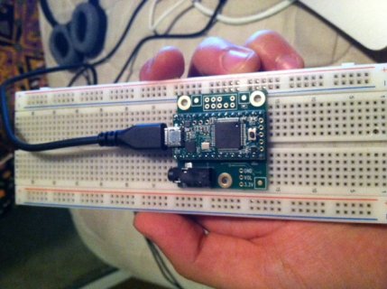
photo(7).JPG

Any ideas?
Thanks!
Zach

--further details--

I have my teensy 3.1 with soldered heads on both sides (I have checked for shorted pins, there are none) plugged into the teensy audio board (i know it is facing the correct direction)

I plugged it into an empty breadboard(with the two sides/columns of pins separated by the breadboards divider of course...) and connected power. Everything was fine. My headphones were plugged in if that is relevant (they definitely work/aren't shorted). I then uploaded the Arduino Examples sketch DialTone_Serial - it uploaded successfully and then teesnyduino prompted me to reset the teensy (press the black button). I did so and the power LED of the teensy turned off, my computer screen made a flash, and then everything shut off.

I've turned my laptop back on - it still works. But when i plug the teensy back in, no red power LED comes on.

Has this happened to anyone? Does this seem as though the board shorted itself? I checked the 3 and 5v pins with voltmeter connectivity and neither are shorted to ground. it just wont turn on.

I seem to have checked every possible hardware fault and I'm certain it isn't anything I am doing - unless my breadboard has a wire stuck inside connecting the parallel rows of power and ground? (kinda doubt it)
Unfortunately, this was the first sketch I uploaded to the teesny with the audio board attached, and so the problem could either be with the board itself or with that patch specifically.

* and the weirdest part of it all is that when i take it off the breadboard and put it back on (along anywhere up or down the board) the on board LED flashes orange for a brief moment, and will occasionally stay on for a few seconds. And when i remove the teesny from the audio board and do it alone, it doesnt f
Any ideas?
Thanks!
Zach
 
Last edited:
Just an update for those who want to use this library with the ADC library: there were some issues and I fixed them, so now they work together:

Teensy 3.0 is compatible, except if you try to use the Audio library ADC input (AudioInputAnalog), because there's only one ADC module so you can't use it for two things.
Teensy 3.1 is compatible. If you want to use AudioInputAnalog and the ADC you have to use the ADC_1 module, the Audio library uses ADC_0. Any calls to functions that use ADC_0 will most likely crash the program. Note: make sure that you're using pins that ADC_1 can read (see pictures above)! Otherwise the library will try to use ADC_0 and it won't work!!
 
Great, looking forward to seeing it.

Do you suppose Freescale would publish a project with Teensy + Arduino, rather than FRDM + CodeWarrior?!

Paul:

This project will be published with using the Teensy (not a FRDM). Projects all use some low cost dev board. We try to use platforms that have an embedded debugger as it is incredibly useful for tricky problems. That being said the Teensy is low cost and you have a library for the WS2812 that can be hacked.

There will be an exercise though of taking the program and porting it another board and another build tool (KDS). This is an important skill for any embedded developer to know how things work under the hood.
 
Hellllllllllo there!!

I'm working on the new revision of THIS project and I'm facing some implementation issues.

few details: I want to implement a 256 analog inputs board w/ 256 addressable LEDs to be used with USB MIDI and audio adaptor board; the analog part is fine, will be done using 17 HCF4067s, the LED part though will be made using WS2812 SMD LEDs (or similar). The thing is: the OctoWS2812 library actually uses pins that are reserved for the Audio Adaptor board, and I would like to keep FULL compatibility with the audio adaptor board on my MIDI controller, so that it will be a piece of cake to turn it from standard USB MIDI to full fledged synth+USB MIDI (+ eventual USB Audio which I'm working on...).

So, is that true? Can I use the octows2812 with the audio adaptor? If not, is there any alternative to control such leds?

Moreover, if a similar question has already been posted, could you kindly provide a link ? Thaaanks guys
 
Hi everyone

I've written a bitcrusher effect (reduce bitdepth of audio on thefly) which works fine; I just shift the bits right x bits, then left x bits, and pipe them through - but it doesn't appear to have any effect until you hit the 8 bit mark or below. Then it starts working but the volume gets louder as you drop down to 2 or 3 bits. This is not correct, the volume should stay the same.

So I thought maybe this is due to the bitshift being a quick but unsatisfactory hack, so I started doing a more intelligent bitdepth maths with floats and caluclating the new value based on the proportion of the samplevalue / maxvalue.

None of this maths is working very well.

Can anyone tell me if the 16bit audio samples are unsigned ints or signed ints? little endian? Something isn't right :-/

cheers

Jon
 
Can I use the octows2812 with the audio adaptor? If not, is there any alternative to control such leds?

I've just looked in the Octo library and there are pin clashes, which mean you wont be able to stack the boards.

It's possible that you could hack the Octo library to use alternative pins assuming all the pins you move have the same functionality supported, but you'd have to hack all the connections about as well.

Why not use two teensy's and sync them up? Your project would certainly benefit from offloading the work on two cpus, and it wouldn't break the bank.
 
Hi everyone
Can anyone tell me if the 16bit audio samples are unsigned ints or signed ints? little endian? Something isn't right :-/

wiki says
PCM audio data is typically stored as signed numbers in two's complement format.

This would explain the problem...can anyone confirm?
 
Well.....that was a waste of time.

replaced my initial working solution:
Code:
for (i=0; i < AUDIO_BLOCK_SAMPLES; i++) {
			sampleSquidge = block->data[i] >> (16-crushBits); // shift bits right to cut off fine detail
			sampleSquidge = sampleSquidge << (16-crushBits); // shift bits left again to regain the volume level.
			block->data[i] = sampleSquidge;
			}


with this one taking into account 2s complement nature of the PCM packet:

Code:
for (i=0; i < AUDIO_BLOCK_SAMPLES; i++) {
			sampleInput = block->data[i]; //signed 2s Complement sample from -32768 to 32767 - sampleInput is int
			sampleInput = sampleInput+32768; //this brings the value of sample input within the range of 0-65535
			sampleSquidge = abs(sampleInput); //sampleSquidge is uint_32t, between 0 and 65535
			sampleSquidge = (unsigned int)sampleSquidge >> (16-crushBits); // shift bits right to cut off fine detail (unsigned int cast suppresses "sign extension" and pulls in zeros)
			sampleSquidge = (unsigned int)sampleSquidge << (16-crushBits); // shift bits left again to regain the volume level. Shift left should always fill with zeroes
			sampleOutput = (int)sampleSquidge -32768; // cast our unsigned int sampleSquidge back to a signed int in sampleOutput, reduced backt to within 2s complement range 16bit PCM
			block->data[i] = sampleOutput; //update the block
		}


No difference in audio output at all. Nothing. Nada. Identical.

Not really noticeable until 10bits kicks in, noise floor lifts, works as expected down to 6 bits then as you approach 4 bits volume begins to increase exponentially. Works great with the auto volume leveller in place though. NIN anyone?

so i figure it was working correctly all along. I then found this video which suggests the same at 6:35, note the same comments about no effect until it gets lower and how it gets louder as you drop the bit level to around 5 or less :

so I'll stick with the first successful implementation which is less cpu heavy and start work on the effect_samplecrusher :) Use them together for 8bit chiptune fun!
 
It's hard to tell what your code actually does when we can't see the type definitions of the variables, particularly for important ones like sampleInput and sampleSquidge.

Your first implmentation looks fine. It could be coded more efficiently, if you're concerned about CPU time for other effects.

Two easy optimizations would be replacing the shifts with a logical AND using a variable with zeros in the lower bits, and loading 4 or even 8 samples into variables, editing them all, and then writing all back out. The Cortex-M4 has a special burst mode access when it detects a sequence of similar load or store instructions, which cuts the time in half for the 2nd and subsequent instructions. Doing 4 or 8 at once also cuts the loop overhead time.

A third slightly more complex optimization would be to load 2 samples at once into 32 bit temporary variables, and then use a logical AND of a 32 bit variable with 2 sections of zeros. The memory and processor are 32 bit, so for some algorithms like this, you can process 2 samples together, for twice the speed... plus the speedups of those other 2 simple optimizations.
 
Well.....that was a waste of time.

Being bass player I would never use a effects pedal that sounds like that, the echo was marginal but the flange and bit crusher are useless for any real bass, plus I wouldn't trust it through my amp, sounds like that thing would blow the horn in my cabnet. Not sure why the guy decided to use a bass as a video test case but he would be much better off using guitar!

Sorry for the rant but a personal pet pevive of mine is when people try to use all these digital effects for a real bass, an EQ is all you need, Mesa Boogie does it right with thier amps no need for a pedal in my opinion. Oh ya get a good bass like my Fender jazz or my new baby Warwick Corvette fretless, let the wood and pickups do the talking for you.
 
Thanks Paul

samplesquidge is uint32 and the other two are int for the record. Sorry I will post more complete code in future.

I am using these effects projects to familiarise myself with c++ better and the Arduino/teensy quirks so I will implement some of those performance tweaks in blocks of 8, and a logical AND solution sounds a little quicker using Constants for the AND values.

Re:bass effects that's not my project :)

The same pedal would works fine for a lead as well though. But I already have a zoom which will do all of that and more. I do want to make a loop pedal with teensy though ;) next project.....
 
Re:bass effects that's not my project :)

I know, sorry if that sounded like i was referring about your project, tried enough pedals for the last 20 years to know that if you want to use effects for bass use a synth instead.

Though if you make a guitar loop pedal using the audio library that would be awesome!!!
 
I've just looked in the Octo library and there are pin clashes, which mean you wont be able to stack the boards.

It's possible that you could hack the Octo library to use alternative pins assuming all the pins you move have the same functionality supported, but you'd have to hack all the connections about as well.

Why not use two teensy's and sync them up? Your project would certainly benefit from offloading the work on two cpus, and it wouldn't break the bank.

Hacking the lib may take some time but seems like the best starting point (and hopefully ending point too :) ); hacking the connection is not that big deal since I'm laying my very own PCBs.

Using two teensy's may be an issue, mainly because I'm planning to sell this project in a modular kit fashion (motherboard with 128 inputs, expansion board with 128 more inputs, LED expansion board w/ psu); the final user should only buy a Teensy (+ eventual audio board) and then add the controls he needs; should he want LEDs he should then buy only the LED expansion board (which will cost a bit since it will have a huge dedicated PSU on it) and add his/her own LEDs. And you all know how expensive potentiometers, sliders, and LEDs in such quantity can be (we are talking as much as 256 controls + 256 LEDs). So if I could spare 20 $ to a potential user that'd be great; I'd rather put a cheaper uc directly on the LED expansion board if needed.

Anyway, thanks for the feedback :)l
 
Hi Guys!

I am wondering how I can chance the sampling rate to 22.05Hz. I adjusted CHIP_CLK_CTRL to 0x0014, but it seems it is not enough. I also changed AUDIO_SAMPLE_RATE. Are there any other chances to the library code? Thanks!
 
bitcrusher effect pull request submitted.

Supports bitdepth and samplerate reduction, sounds like an old console game when you drop the settings low :)

Edit: sample rate squisher has a functional limitation of minimum 345hz due to the 128 sample buffer.
 
Last edited:
Example project for Bitcrusher added with Compressor example as well, however I have noticed some bugs / sensitivities in the DSP AVC (herein referred to as the compressor, for that is what it is).

1) if i set the max gain to 0db, when you turn off the compressor the attack seems to hang in a regular loop. Setting the max gain to -6db or -12db does not cause this issue.
2) Not a fault at all, but I've noticed that the sonic result of the compressor varies a lot according to the mixer gains you have to apply. If you have multiple samples and set lots of mixers up at a lower level (0.7 each for example) to accommodate the possibility of all of them firing at once, the compressor has a very different result to if you set them to max gain. This was very obvious when switching between my main project and the effect example project which doesn't feature any mixers at all. The settings in the example file sound great on my main project but rubbish on the example. :)

In summary : You'll need to do a lot of peak level investigation on complex projects, to ensure that your audio is at a reasonable level before it hits the DSP, if you wish to use the AVC properly.
 
Hi Guys!

I am wondering how I can chance the sampling rate to 22.05Hz. I adjusted CHIP_CLK_CTRL to 0x0014, but it seems it is not enough. I also changed AUDIO_SAMPLE_RATE. Are there any other chances to the library code? Thanks!

Let me rephrase my question.

I am doing an experiment with teensy and the audio board. I use a function generator to input a signal with a certain frequency into the microphone input.

I calculate the FFT of the signal and identify its coefficient with the highest amplitude. Such a coefficient is printed in the console.

In the default setting (40.1Khz sampling rate), I can identify signals up to 22KHz, as expected. If I change CHIP_CLK_CTRL to 0x0014 (22.05Khz sampling rate), I can identify signals up to 11KHz, as expected too. What is strange is that the FFT resolution did not change. In both cases each coefficient represents 43Hz for a 2014-point FFT (44.1KHz / 1024). However, changing the sampling rate to 22.05KHz should double the resolution to 21.5Hz (22.05KHz / 1024).

Am I missing something? Thanks!
 
I am wondering how I can chance the sampling rate to 22.05Hz. I adjusted CHIP_CLK_CTRL to 0x0014, but it seems it is not enough. I also changed AUDIO_SAMPLE_RATE. Are there any other chances to the library code? Thanks!

In theory, that should do it.

In practice, there is a LOT of code in the audio library that's never been tested at any rate other than 44100. Odds are good it has many little dependencies on 44100 Hz (like the fact that CHIP_CLK_CTRL is hard-coded). Ideally, all of those should be found and fixed, so they scale properly and automatically when AUDIO_SAMPLE_RATE is changed. If you find and fix any, please send a pull request on github!
 
Let me rephrase my question.

I am doing an experiment with teensy and the audio board. I use a function generator to input a signal with a certain frequency into the microphone input.

I calculate the FFT of the signal and identify its coefficient with the highest amplitude. Such a coefficient is printed in the console.

In the default setting (40.1Khz sampling rate), I can identify signals up to 22KHz, as expected. If I change CHIP_CLK_CTRL to 0x0014 (22.05Khz sampling rate), I can identify signals up to 11KHz, as expected too. What is strange is that the FFT resolution did not change. In both cases each coefficient represents 43Hz for a 2014-point FFT (44.1KHz / 1024). However, changing the sampling rate to 22.05KHz should double the resolution to 21.5Hz (22.05KHz / 1024).

Am I missing something? Thanks!

http://forum.pjrc.com/threads/24793-Audio-Library?p=48465&viewfull=1#post48465

This code needs tweaked to use the latest library code but gives much higher resolution - uses parapolic interpolation on the FFT.
 
Last edited:
http://forum.pjrc.com/threads/24793-Audio-Library?p=48465&viewfull=1#post48465

This code needs tweaked to use the latest library code but gives much higher resolution - uses parapolic interpolation on the FFT.

Awesome! Thank you very much. It is fun to see how the resolution improved with this technique.

But, I also need to slow down the sampling rate (and consequently get an improved resolution). I am stuck in the following situation: Although CHIP_CLK_CTRL does reduce the sample rate, the resolution is not improving. I am not sure why it is happening. Is it possible that although the sample rate was changed from 44.1K to 22.05K, the library is still receiving data at 44.1KHz? Possibly with two consecutive readings being identical?

Thanks. Gustavo.
 
Status
Not open for further replies.
Back
Top