Teensy 3.x Vusb location in Schematic

Status
Not open for further replies.

embedded-creations

Well-known member
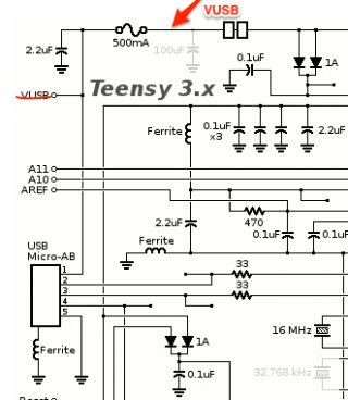
Hi Paul, I'm pretty sure the location of VUSB in the Teensy 3.x schematic is in the wrong place, not matching the board. I believe it should be on the other side of the fuse. I had suspicions looking at the 3.0 board, but the fab process on the 3.1 is clearer and I can follow the traces all the way to Vin. This is good news for me and my board design as it means I can cut the trace and still have access to fused power from USB without requiring any SMT soldering.

Teensy_and_Teensy___Schematic_Diagrams-8.jpg

Please confirm!

Thanks,
Louis
 
I was planning to use the Teensy attached to an self-powered USB hub and use VUSB to power and control some relays (4x 20mA).

Does the placement of the fuse mean that the hub is safe when the relays play havoc but the Teensy might get killed?
And that I am restricted to 500mA total (Teensy + relays + stuff)?
 
Hi Paul,
I'm having a problem with my teensy 3.1. This is my situation, I'm doing a connection between my teensy and an Arduino UNO trough bluetooth, I'm using Serial1 to connect teensy with the bluetooth (BlueSmirf), I was using an USB port to feed the Teensy, and it was working just fine, but now I'm using an external power supply because the board has to be in the person, I separated the VUSB and VIN pins, I don't know if this was necessary... now I'm trying to bring information from the Teensy to the Arduino but its not working...do you have an idea why this is happening, I'm confuse, I don't know if its necessary to configure something else in the teensy...
thanks for the help.
 
I was planning to use the Teensy attached to an self-powered USB hub and use VUSB to power and control some relays (4x 20mA).

The relay board says 10-20 mA, but from the size of those relays, my guess is the 10 mA is only to turn on the LED inside each optocoupler, which appears to turn on a little transistor that then turns on the relay. My guess is the board will draw quite a lot more current from the VCC pin when those relays are on.

Of course, that's all guesswork on my part, from only those photos. Like most cheap Chinese products, there's little reliable info. You'll probably only find out the real current using a multimeter.

Does the placement of the fuse mean that the hub is safe when the relays play havoc but the Teensy might get killed?

It's always difficult to predict exactly how things will fail, especially when using 2 other non-PJRC products, each made as cheaply as possible in China and sold without good technical specs or schematics.

But I'd guess too much current will simple drag to the 5V power down to a level where things don't work, or fail mysteriously. I'd recommend monitoring the 5V power with a multimeter.

And that I am restricted to 500mA total (Teensy + relays + stuff)?

TL;DR = yes, you're limited to 500 mA, if the hub is "self powered" (which in the USB specs means it has a power adaptor).

I usually use the terms "powered" and "unpowered", which aren't as formal as the USB spec, but people see to find less confusing in conversation. If the hub is unpowered, it may not be able to deliver 500 mA.

Also, you should be aware the PTC "fuses" are crude devices. They're merely a resistor that increases value. They work by having metal particles mixed into a ceramic that thermally expands, adding more gaps between the metal as it gets hot. Before it gets hot, a pretty incredibly large current can flow. Of course the larger the current, the faster is heats. Because it's only a resistor, the current is never shut off. The PTC only adds more resistance in series with Teensy, until the circuit reaches some equilibrium based on the input voltage, PTC resistance and whatever is trying to draw so much current. That's a lot better than a dozen amps flowing through the thin PCB traces and burning them, but it's certainly not a highly precise process. It's only a little chunk of thermally expanding ceramic with little metal bits mixed in.
 
yes, you're limited to 500 mA, if the hub is "self powered" (which in the USB specs means it has a power adaptor).

I usually use the terms "powered" and "unpowered", which aren't as formal as the USB spec, but people see to find less confusing in conversation. If the hub is unpowered, it may not be able to deliver 500 mA.
My question was not were clearly phrased. I'll try once more :)

I will use a hub with a power adapter, it is an D-Link DUB-H7. This hub can deliver 500mA on all ports. Two of its ports can also deliver up to 1200 mA.
The Teensy will be attached to this hub (I will choose the port after measuring the relays).

The question:
Is there a pin on the Teensy where I can tap the hub's power (up to 1200 mA) directly?
Or do I have to take the USB cable apart and tap the power there to operate the relays?
 
On the Teensy 3.x, the VUSB pin (the one that is in towards the USB connector) is connected to USB power after the PTC polyfuse -- relay activation current will therefore flow through the polyfuse. Those relays draw ~ 90 mA. I don't know the characteristics of the polyfuse component to know if is 'happy' with ~ 130 mA total (Teensy + Relays + ...).

Also, on many of those relay boards, you can separate the relay power from the input signal power -- there's a jumper JD-VCC that separates things. My suggestion (for reliability) is to power the relays directly from the USB (i.e. not the VUSB pin on Teensy). I don't know what's on those boards, but you might want to ensure that there's a cap (0.1 .. 1.0 uF) physically on the board's VCC power to GND to avoid transient voltage spikes on the long USB cable when the relays are switching off.
 
Status
Not open for further replies.
Back
Top