analog input 'saturated'?

Status
Not open for further replies.

BJB

Well-known member
Good People,

Am reading a ACS712-5, powered by 5V, using a buffer (simple V follower op amp). The current sensor provides good V, measured at analog pin on the Tnsy 3.1, over the 250mA range, but ADC results always indicate full the full scale count for whatever res that I have set for the ADC.

Am using the default 3V3 ref.

Code attached, and ckt.jpgschem image. Please advise - am certain that I am overlooking something painfully obvious.
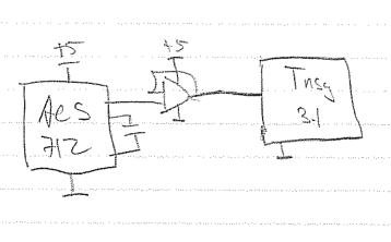
Thanks much.
 

Attachments

  • ts_code.cpp
    1.1 KB · Views: 152
Doh - ignore my stupidity - wrong aref setting left over from a previous test run.

Just call me Mr. Facepalm.
 
I thought only the digital pins were 5V tolerant on the Teensy 3.1 and not the analog pins. (!!??)
Correct.
So, if the current being sensed by the ACS712 is low, the output voltage will be low and the teensy 3.1 will be fine.
However, if the buffer op-amp swings to the positive rail at any point on startup, the Teensy 3.1 will be damaged.
Similarly, if the current being sensed is high enough, the ACS712 can output up to 8V, which will result in 5V (more accurately, the maximum output voltage swing of the op-amp, which varies by model) being seen by Teensy 3.1.
If it happens to be a rail to rail op-amp, that would be bad. If the op-amp can swing to 1.5V from the rail, that would be 3.5V (also bad).
A resistive divider on the output of the op-amp that drops 5V to 3V3 would seem to be a useful precaution.
 
Yup, an easy solution is to power the op-amp with 3.3V instead of 5V. Or not use it at all.

The trick with the ACS712 board is to set the gain and offset (which are VERY sensitive to play with) but the minimum gain is about 4.3. The typical output of the ACS712 is 185mV/A. So at 250ma, the output of the ACS712 will be about 47mV. With the minimum gain, the output to the teensy will be about 200mV. For AC current, the offset needs to be set as closely to 1.55 volts as possible, assuming the ADC is set for DEFAULT reference (3.3V supply voltage). With this reference, the gain can be increased to 6 to get +/- 1.5V to the teensy at 250mA max sensed current.

With a DC current source, the reference should be set to zero, or as close as the pot will allow. With this setting, the maximum gain can be set to 13 to get 3.3V to teensy at 250mA max sensed current.

I suggest using a voltmeter or oscilloscope to set the offset and gain BEFORE connecting it to your teensy.

;)
 
All very true and probably mucho good advice, so do not try this at home kids. But not an issue for this implementation because:
1. TL431s driving shunt power FETs if >3.4V to protect ADC pins.
2. Non-linear range processing in front end where need res + linearity over first 250mA, but log 'compress' higher range up to 4.85A, which is only used to quantify a fault current.
3. 3.3V is dedicated to powering two ASICs and driving some remote LEDs external to the combiner box. And it seems to be used by the chip too...
4. The 5.001V comes from a nice LDO that must not see the noise on the 3.3V, and is powered by Li btty.
 
Status
Not open for further replies.
Back
Top