Decreasing noise on Teensy ADC

Status
Not open for further replies.
JBeale, your results seems unreal (good), but we transfer the data via serial as they are taken, so serial is on...see my graph i plotted, i would be very happy if teensy would perform as in your report...
When we use BT module it is alot better but still nowhere near your results.
I think we initially commented your report and i said to gbathree, this is good so we decided on using Teensy 3.0, then later see my screen capture...
Do you have raw data/count stream saved somewhere and can you plot it?
 
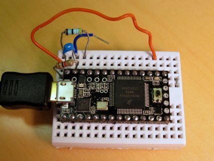
I didn't store the data but this is the setup I used. notice it's just USB going in and no connection to any other circuit boards; no serial, no bluetooth etc. I recommend you trying exactly my setup, with my code- should take just a few minutes- and see what you get. If you see results like mine, then you know the problem is not in the Teensy 3 by itself but maybe some interaction with external devices. Getting clean signals at sub-millivolt levels becomes more difficult the more interconnections you have. Systems with high-res ADCs usually sit on their own clean ground planes with their own clean power supplies separate from the digital systems. The best ones use opto-isolated digital I/O to avoid noise coupling to the outside. Putting a radio transmitter (BT module) nearby sub-millivolt signals will also have some effects.

IMG_2534.JPG
https://picasaweb.google.com/109928236040342205185/Electronics?noredirect=1#5795546092126071650
 
JBeale - we definitely read that through before we started, that was really helpful. We were hoping perhaps there were other workarounds.

stevech - Not really. If it was true 16 bit, our signal would look great even with only 2000 points of resolution. We are considering addressing this by expanding the range dynamically for each measurement - setting the comparator for the op amp based on the first point in the measurement (I think I've got my lingo right here, Robert correct me if I'm wrong please). We have to do it dynamically because one measurement could be 30,000 - 32,000 while the next is 2000 - 4000. That would increase the resolution, but it may create other problems and make the device harder to develop on.
Could AREF be set to a value near the mean of the real voltages (given the offset) to improve precision?
 
T3 ADC is more noisy now than in 2012?

UPDATE: this is interesting. I still have that T3 on the same breadboard, and I set up the same circuit I had before as per the photo. I ran the same code as I used back on 4-OCT-2012 and realized that since I am now using Teensyduino 1.18, some things have changed. For example, although I had called "analogReference(INTERNAL)" it apparently works differently now, causing my 2.176V signal to be out of range (65535). So I changed that to analogReference(EXTERNAL) and it gives me about the right values, except I am getting 5x faster ADC readings (using analogReadAveraging(16) which I previously left at whatever the default was) and also my noise is about 2x larger (St.Dev = 2.1 instead of 1.1).

I gather Paul made the ADC work faster with some Teensyduino update in the past 1.5 years, but that may have also increased the noise level (?) I would not be surprised if 5x increased ADC speed resulted in 2x higher noise, seems plausible. If that is what happened, maybe there could be a compile-time switch to select the ADC mode to either the current "faster and noisier" or the original circa 2012 "slower and quieter".

Today's result (26-FEB-2014) with Teensyduino 1.18 :
Code:
# Samples/sec: 10976.95 Avg: 43707.07 Offset: 43.83 P-P noise: 29 St.Dev: 2.077
# Samples/sec: 10976.95 Avg: 43707.02 Offset: 43.77 P-P noise: 27 St.Dev: 2.080
# Samples/sec: 10976.95 Avg: 43707.04 Offset: 43.80 P-P noise: 44 St.Dev: 2.084
# Samples/sec: 10976.95 Avg: 43706.93 Offset: 43.68 P-P noise: 32 St.Dev: 2.134
My result from 04-OCT-2012 with Teensyduino (unknown version number, whatever was current then)
Code:
# Samples/sec: 2236.64 Avg: 43583.83 Offset: 20.92 P-P noise: 9 St.Dev: 1.116
# Samples/sec: 2236.64 Avg: 43583.67 Offset: 20.76 P-P noise: 8 St.Dev: 1.123
# Samples/sec: 2236.14 Avg: 43583.81 Offset: 20.89 P-P noise: 8 St.Dev: 1.117
# Samples/sec: 2236.64 Avg: 43583.73 Offset: 20.81 P-P noise: 10 St.Dev: 1.107
Code which I tried out today
Code:
// Analog input test for Teensy 3.0    Oct 4 2012 - Feb 26 2014 J.Beale
// Setup: https://picasaweb.google.com/109928236040342205185/Electronics#5795546092126071650

#define VREF (3.266)         // ADC reference voltage (= power supply)
#define VINPUT (2.176)       // ADC input voltage from resistive divider to VREF
#define ADCMAX (65535)       // maximum possible reading from ADC
#define EXPECTED (ADCMAX*(VINPUT/VREF))     // expected ADC reading
#define SAMPLES (10000)      // how many samples to combine for pp, std.dev statistics

const int analogInPin = A0;  // Analog input is AIN0 (Teensy3 pin 14, next to LED)
const int LED1 = 13;         // output LED connected on Arduino digital pin 13

int sensorValue = 0;        // value read from the ADC input
long oldT;

void setup() {    // ==============================================================
      pinMode(LED1,OUTPUT);       // enable digital output for turning on LED indicator
      analogReference(EXTERNAL);  // set analog reference to internal ref
      analogReadRes(16);          // Teensy 3.0: set ADC resolution to this many bits
      analogReadAveraging(16);    // average this many readings
     
      Serial.begin(115200);       // baud rate is ignored with Teensy USB ACM i/o
      digitalWrite(LED1,HIGH);   delay(1000);   // LED on for 1 second
      digitalWrite(LED1,LOW);    delay(3000);   // wait for slow human to get serial capture running
     
      Serial.println("# Teensy 3.0 ADC test start: ");
} // ==== end setup() ===========

void loop() {  // ================================================================ 
     
      long datSum = 0;  // reset our accumulated sum of input values to zero
      int sMax = 0;
      int sMin = 65535;
      long n;            // count of how many readings so far
      double x,mean,delta,sumsq,m2,variance,stdev;  // to calculate standard deviation
     
      oldT = millis();   // record start time in milliseconds

      sumsq = 0; // initialize running squared sum of differences
      n = 0;     // have not made any ADC readings yet
      mean = 0; // start off with running mean at zero
      m2 = 0;
     
      for (int i=0;i<SAMPLES;i++) {
        x = analogRead(analogInPin);
        datSum += x;
        if (x > sMax) sMax = x;
        if (x < sMin) sMin = x;
              // from http://en.wikipedia.org/wiki/Algorithms_for_calculating_variance
        n++;
        delta = x - mean;
        mean += delta/n;
        m2 += (delta * (x - mean));
      } 
      variance = m2/(n-1);  // (n-1):Sample Variance  (n): Population Variance
      stdev = sqrt(variance);  // Calculate standard deviation

      Serial.print("# Samples/sec: ");
      long durT = millis() - oldT;
      float datAvg = (1.0*datSum)/n;
      Serial.print((1000.0*n/durT),2);

      Serial.print(" Avg: ");     Serial.print(datAvg,2);
      Serial.print(" Offset: ");  Serial.print(datAvg - EXPECTED,2);
      Serial.print(" P-P noise: ");  Serial.print(sMax-sMin);
      Serial.print(" St.Dev: ");  Serial.println(stdev,3);
} // end main()  =====================================================
 
Last edited:
UPDATE2: On second thought, no need to have such a compile switch. If I simply average 5 samples together, using the current Teensyduino 1.18 code, it is still faster overall than the 2012 version (3343 samples/sec vs 2236) and even quieter (STD = 0.98 vs 1.1). Best of both worlds.

In the code listed above, I just changed x = analogRead(analogInPin); to
Code:
        x = 0;
        for (int j=0;j<5;j++) {
          x += analogRead(analogInPin);
        }
        x /= 5;

and I got this result:
Code:
# Samples/sec: 3344.48 Avg: 43733.19 Offset: 69.94 P-P noise: 9 St.Dev: 0.983
# Samples/sec: 3344.48 Avg: 43733.03 Offset: 69.79 P-P noise: 8 St.Dev: 0.982
# Samples/sec: 3344.48 Avg: 43733.03 Offset: 69.78 P-P noise: 8 St.Dev: 0.974
# Samples/sec: 3343.36 Avg: 43733.09 Offset: 69.84 P-P noise: 8 St.Dev: 0.963
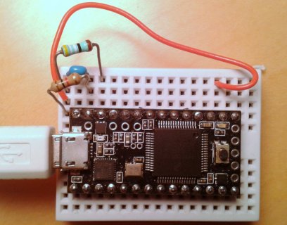
Circuit as tested today, using T3 with three components: 1k, 499 ohms, 0.1 uF cap. With no cap, you get STD = 1.9 or so, and the average value of the reading decreased about 9 counts. In other words, the source impedance changes the ADC offset and/or scale factor.
T3-ADC-test.jpg

Note: there is some variation between individual units. I plugged a second Teensy3.0 unit into the same breadboard and got about 25% more noise. This was with the same software and hardware setup.
Code:
# Samples/sec: 3343.36 Avg: 43722.89 Offset: 59.65 P-P noise: 9 St.Dev: 1.243
# Samples/sec: 3344.48 Avg: 43722.77 Offset: 59.53 P-P noise: 12 St.Dev: 1.234
# Samples/sec: 3343.36 Avg: 43722.75 Offset: 59.50 P-P noise: 9 St.Dev: 1.242
# Samples/sec: 3343.36 Avg: 43722.75 Offset: 59.50 P-P noise: 10 St.Dev: 1.242
However, changing from 96MHz overclock down to 48 Mhz improves noise a bit, as well as strangely changing the average value; apparently system clock has some effect on the offset/scale factor.
Code:
# Samples/sec: 3281.92 Avg: 43714.00 Offset: 50.75 P-P noise: 9 St.Dev: 1.077
# Samples/sec: 3281.92 Avg: 43714.05 Offset: 50.81 P-P noise: 10 St.Dev: 1.068
# Samples/sec: 3281.92 Avg: 43714.09 Offset: 50.84 P-P noise: 11 St.Dev: 1.078
# Samples/sec: 3281.92 Avg: 43714.09 Offset: 50.84 P-P noise: 9 St.Dev: 1.074
Dropping down to 24 MHz further changes the average value (offset?) but now noise is slightly worse.
Code:
# Samples/sec: 2958.58 Avg: 43699.76 Offset: 36.52 P-P noise: 9 St.Dev: 1.147
# Samples/sec: 2961.21 Avg: 43699.89 Offset: 36.64 P-P noise: 9 St.Dev: 1.157
# Samples/sec: 2958.58 Avg: 43699.68 Offset: 36.44 P-P noise: 9 St.Dev: 1.148
# Samples/sec: 2959.46 Avg: 43699.84 Offset: 36.59 P-P noise: 9 St.Dev: 1.164
...and check this out, connected to a different USB port on the PC, noise level drops:
Code:
# Samples/sec: 2960.33 Avg: 43704.04 Offset: 40.79 P-P noise: 7 St.Dev: 0.769
# Samples/sec: 2959.46 Avg: 43704.21 Offset: 40.97 P-P noise: 6 St.Dev: 0.781
# Samples/sec: 2958.58 Avg: 43704.21 Offset: 40.96 P-P noise: 5 St.Dev: 0.772
# Samples/sec: 2960.33 Avg: 43704.36 Offset: 41.11 P-P noise: 6 St.Dev: 0.776
I'm not too surprised by the variation; Vdd is 3.268 V so 1 LSB = 50 uV. The noise on the USB +5V rail can be many mV so some will likely leak through the regulator & filter caps to the ADC.
 
Last edited:
I'm surprised that you are getting decent noise levels with USB connected. I saw considerable improvement when I switched to batteries.
When I had done a test before, I was using IntervalTimer to sample periodically, and was wondering if the interrupt triggers were potentially inducing noise.

I was writing the data to an sdcard, and I was also concerned that the power draw from the block writes to the sdcard were also inducing noise. Hmmm, maybe putting a cap on the mini sdcard adapter? I was hoping to minimize noise by using a voltage reference chip, but never got that far. I'm really curious to see the noise level on the differential ADC inputs.

I have a similar issue, and quite common in measuring physiology, biology, etc. You have slow-varying signals that are akin to DC signals, and you have fast-varying signals that are akin to AC signals. You don't really want to split them up and amplify them separately, cause you necessarily decouple them, and you really need to see the interactions. And, once you decouple them, you may mask or imbue relationships with the signal conditioning that are difficult to know.
 
As soon as I connect additional circuits to the board, the noise will increase, so my simple resistive divider referenced to the on-board 3.3V rail is kind of a best-case experiment. In most real-life applications I would expect a battery supply to work better, as you found.

Note that I have set analogReadAveraging(16); and then on top of that I average 5 of those for each data point, so each ADC value in my program is really the average of many separate ADC reads. But if 3000 samples per second is enough, then it works just fine. You can of course go faster at the expense of noise. If I set analogReadAveraging(1) and no additional averages in my code, I get 18281 samples per second (6x faster) with STD around 7.5 and pk-pk noise around 120 for a set of 10000 samples.

Going to analogReadAveraging(16) and no additional averaging in my code, I get 10718 sps, STD 2.1, pk-pk 27 so the noise is much improved, and with less than a factor of 2 change in sample rate.
 
Last edited:
Awhile back, someone posted some testing that seemed apparent that averaging in the sketch produced slightly better results than averaging within the ADC. My understanding is that analogReadAveraging(16) uses a feature in the ADC to take 16 samples as fast as possible (DMA?) and averages them.

Which I guess might make sense, as it may take longer to do multiple samples in the sketch, so you would necessarily be averaging over a longer time-span.

Might be interesting to take the median of the multiple samples. It might be better to just take lots of samples and do the signal conditioning post-hoc using statistical methods and other things.
 
Last edited:
I agree that the work Paul put into making the Teensy boards as good as they are is humbling. Manufacturers are free to create all sorts of 'best case' scenarios to support their claims re: performance, but those conditions may be completely unrealistic in real life - whether it means turning off most other chip functions, extensive buffering of inputs, or other tricks of the trade, I'll wager a lot of engineering goes into tickling out the last bit of performance to make the marketing specifications legitimate.

That said, the specifications of the K20 are impressive, there are few chips out there that offer 12-13 bits of realistic ADC performance. There are limits, such as unipolar-only operation, but never underestimate the benefits of a general-purpose CPU allowing easy verification of what the measurements are. You don't have to deal with an external ADC, nor the vagaries of register-settings, bus communication, etc. which simply add to the complications, making trouble-shooting that much harder. That said, for my application, I am pursuing a MCP3911-based solution, simply because the chip allows me to do things that the Teensy 3.0 couldn't do.

The Teensy 3.1 offers options that make energy measurements much easier - you can finally conduct 2 measurements concurrently, use a PGA on one channel, etc. but the library still needs to be built out to support all these options. For the unipolar input alone, my decision has hence been to go with an external chip even though the right front end could make the Teensy 3.1 a viable option. Time will tell if it was the right decision as even dual 12-bit operation may be sufficient to characterize a power signal quite well.
 
Source impedance of your signals makes a huge difference.

On Sunday and part of Monday, I worked on the bed-of-nails test fixture for the upcoming OctoWS2811 shield (the reason I wasn't very active on the forum nor committing much code on those days). I was once again reminded how uncooperative electrons can be...

That tester has three 74HC4051 analog mux chips. The 16 wires from the two RJ45 connectors, and 5 more ground and power points, are muxed from the 24 pins to 3 analog inputs on a Teensy 3.1 that runs the test. Each mux output has a 2.2K resistor to ground and a 6.8K resistor to +3.3V, so if the pin is floating, it will measure 0.81 volts.

Because the pins can be driven to 5 volts, I wanted a roughly 5:1 resistor divider between the mux output and ADC input, so I could use the 1.2V internal reference and be able to measure up to 6V. I wanted to resistor divider to be higher impedance, so it wouldn't change the "floating" voltage too much.

Initially I tried a 220K and 47K resistor. Knowing this would be terrible, I had designed a 100 pF capacitor in parallel with the 47K resistor, hoping that would make the ADC a little happier with at least a lower impedance at really high frequency (like the 6 MHz internal clock the ADC uses).

But the electrons didn't cooperate with my plan.

Really, I didn't need great performance for this. I almost just went with it as-is. Probably the worst issue was the "noise" was really terrible for measuring close to zero volts. I didn't do a lot of detailed experimenting and analysis (my goal was to get it working well and return to developing the audio library). My gut feeling was that I was running into leakage current from the unused digital circuitry on those pins, which of course flows out the pin and creates a small phantom voltage as it passes through the high source impedance before getting to ground.

Ultimately I changed the resistor divider to 10K and 2.2K, which does alter the floating voltage quite a bit, but that's a lot easier to deal with in software than a non-linear response. Even with a 2K source impedance (when driven by low impedance from the Octo28 boards's 'HCT245 or the power/ground pins that are low impedance), I was seeing less than 12 effective bits, maybe about 10 or 11. But far better than it needed to be, and not depending software kludge, which makes me happy.

Great analog circuit design is tough. So many things matter. But low source impedance is particularly important, especially when feeding the signal into an ADC pin that has unused digital stuff connected.
 
One more comment: the resistance of the mechanical pressure contacts made by a solderless breadboard such as I have been using can fluctuate at the milli-ohm level. That translates into some microvolts of noise if you have a few mA currents flowing, as I do through my 1.5k ohm resistive divider to the +3.3V rail. So for the cleanest signals, you are well advised to use only soldered connections (or at least clean and physically large contacts). I think it is this effect that caused some of the differences in std.dev. that I reported yesterday, it was just a question of handling the board, slightly bumping the resistors and making the contacts a bit more or less noisy.
 
I have confirmed ADC numbers similar to JBeale's on a standalone teensy. So if you see worse performance, look to the surrounding noisy circuitry or environment for the problem. Also verify that you are doing as many averages and that the USB serial monitor program isn't running (battery operation would be even better).

I found that by setting averaging to 4 and then taking the median (not mean) of 64 of those values, I could get a std dev of .19, ie better than 16 bits, 95% of the time.
 
Last edited:
I have just wired my first T-LC into a project. It is much faster than the Feather M0 - about 5X faster!!! taking 4096 analog samples and decimating! I did discover that if a 2.2 uF electrolytic capacitor was placed across AREF-GND the range of readings went down from ~250 counts to ~13-15 counts. I have not optimized the valve. It is supplied by a shunt regulator at 3.000v. A cap across the analog input does not help much, but it is connected to a pressure sensor with unknown output impedance.

May be worth a try if you are not doing it yet.
Cheers!
 
I am getting much more noice at about the center area, i.e at 14bit around 8000, at 12bit at around 2000. Why is this?

The reference voltage is 3.3 from the board (teensy 3.2) connected to 10 Kohm potentiometer.
 
Yes I think I need to experiment something like that next. I wonder though why is the problem worst at about center position of the potentiometer. there is certain positions where the noice is really bad. it could be a jump about 200 (at 14 bit) every couple of seconds or faster repetition.
 
The source impedance seen by the ADC input is the resistance of the upper half of the pot in parallel with the lower half. So it logically has its maximum at center position. And noise is among others proportional to the source impedance. Using a 1k Pot or an OP amp as a buffer between the pot and the ADC input might improve the situation. Second noise source is the 3.3V thing which is not a clean reference since digital currents are sourced and sinked from it. That's the noise which increases with the pot going upwards. But since the upper pot end and VREF see the same noise, it ideally compensates itself. Third source is dirty ground (again because of digital currents). That's the noise which increases with the pot going downwards. Using AGND for the lower pot end (and the 10nF capacitor from the wiper) might already reduce this.
 
This is how it looks like. https://vimeo.com/292294446

This is without filtering the raw readings, but just realised I am reading around 10 kHz and printing 100 Hz, so it could have something to do that this also. Normally I am using a long sliding filter, but noticed the noice also trough it, so now testing.

analogReadAveraging(32); cleans up the blue, but does not help much on the red. I can also find position for the blue so that it does the same.
 
The 10nF capacitors cleaned nicely some of the noise, https://vimeo.com/292309614 , but the main problem remains. I think the problem must be on the potentiometers, they are old. this is a probably 20 years + old broadcast lens. Must change the potentiometers next.
 
The 10nF capacitors cleaned nicely some of the noise, https://vimeo.com/292309614 , but the main problem remains. I think the problem must be on the potentiometers, they are old. this is a probably 20 years + old broadcast lens. Must change the potentiometers next.

WTF??? How can one prototype new projects with old parts? During the development phase of a new project, new parts should be used to be already very close to what will happen in later mass production.
 
Status
Not open for further replies.
Back
Top