How are you Mounting Teensy 3 / 3.1 ?

Status
Not open for further replies.

RichardFerraro

Well-known member
How are you folks mounting the Teensy 3/3.1 ?

I haven't figured out a good way.

Double stick tape is bad if you want to use the underside pads.
No screw holes.

Complicating the issue is during development when you need to make modifications, yet your design has to be small and void of pesky connectors.

Thanks,

Richard
 
I prototype on a breadboard using a Teensy with female headers with long pins.

For permanent installations, I've typically soldered .1" pin headers to perf board and soldered the Teensy to the headers. This has a much lower profile than using female sockets. In my latest creation, I removed the plastic spacer after soldering the pin headers so the Teensy rests directly on the perf board. The holes are only plated on the opposite side from the Teensy.

I've got some small machine headers and pins intended for making smaller connectors, but I haven't used them much yet. The insertion force required seems a bit high, so I'm not sure how well they'd work if more than a few were used to anchor the Teensy. Might work to use just four at the corners.

[Edited: Pay attention to the number of mating cycles specified for your connectors. The machine headers I have wear out pretty quickly. Flaky connectors are not much fun.]
 
Last edited:
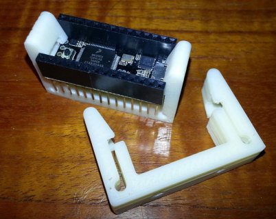
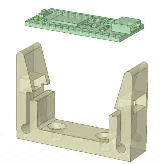
I designed these little 3D printed Teensy 3.0/3.1 holders for small projects.

20140213_172421.jpg 2-13-2014 6-05-09 PM.png
Instead of just straight pin headers, I soldered on Arduino style socket header blocks with long pins.
THis allows me to still use the Teensy in a breadboard, or directly with jumper wires.
There are two screw mounting holes in the base, and access for the USB port through the side.
It's printed from ABS plastic, which is tough and has good flexibility.

Here is the .stl file: View attachment TeensyHolder108.zip
 
I designed these little 3D printed Teensy 3.0/3.1 holders for small projects.

View attachment 1445 View attachment 1446
Instead of just straight pin headers, I soldered on Arduino style socket header blocks with long pins.
THis allows me to still use the Teensy in a breadboard, or directly with jumper wires.
There are two screw mounting holes in the base, and access for the USB port through the side.
It's printed from ABS plastic, which is tough and has good flexibility.

Here is the .stl file: View attachment 1447

Very nice thank you! Think it will fit the 3.2?
 
Hmmm, this is an old thread that got brought back to life.

One way that I've thought about is using small protoboards, such as this one that extends out 0.1" on both sides, and has screw holes for mounting: https://www.tindie.com/products/DrAzzy/1x2-prototyping-board/.

The new prop shield is the same width and just a bit longer: http://www.pjrc.com/store/prop_shield_lowcost.html.

The Adafruit small mint time perma-proto board is another way if you need power rails: https://www.adafruit.com/products/1214.
 
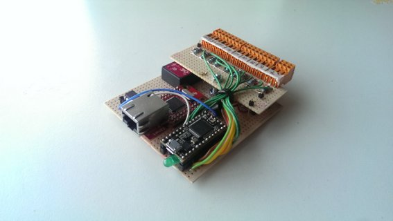
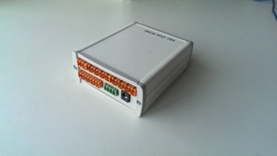
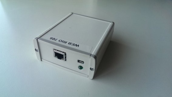
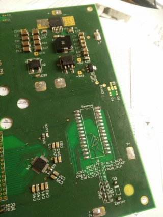
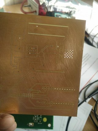
For most prototypes I just mount them on perfboard which I cut to fit in an aluminum casing. For larger batches (>10) I order PCBs.

webriofront.jpg

webriocasedfront.jpg

webriocasedback.jpg

I'm switching most of my prototypes to DIN rail casing now, those cases have precut openings for the connectors.
 
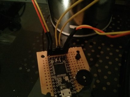
In my latest creation, I removed the plastic spacer after soldering the pin headers so the Teensy rests directly on the perf board. The holes are only plated on the opposite side from the Teensy.

@pictographer -- can you share a photo of this please?
 
@colt, sorry, I didn't take a picture of the side view before i assembled it and the gadget is currently in use. This is the best I've got:

white_noise1.jpg

You can use a pliers to move the pins one-by-one in a pin header. After they are moved, the friction required to move them again decreases. After loosening the pins this way, solder them as normal to the Teensy. The fewer the pins in the header, the easier it will be to remove the plastic. Use a spudger or a plastic spoon to gently slide the plastic off the pins.

Unless you want to decrease the thickness of the assembly by a couple of millimeters or so, runs the risk that you'll crack a solder joint, makes head dissipation worse and is pretty much a waste of time, but if you need the space, it works. :p

In case anyone is curious, the gadget is a white noise generator. The Teensy simply delays for a random interval before toggling an output. The output controls a transistor that drives a speaker. A variable resistor controls the volume. It's all mounted in a nice tin can with the speaker at the top in a plastic frame. The Teensy's LED produces a nice glow in the plastic ring. Works beautifully.

Don't ask for the schematic. I didn't keep it. I made the circuit by trial-and-error. It works, but you can find far better on the net.
 
@Xenoamor --- would really like to understand what you are doing and an image with the Teensy if possible. Thank you.
 
@Xenoamor --- would really like to understand what you are doing and an image with the Teensy if possible. Thank you.

I'll get an image of this tomorrow when I'm back at work for you
The teensy is actually mounted on the underside of the board with the button sandwiched between the Teensy PCB and this PCB. This is due to some pretty tight vertical height requirements.

It's hand soldered and not reflowed though. I doubt you can reflow a teensy
 
It would have been awesome if the Teensy came with castellated mounting holes.

So have you seen the small adapter board done by @HWGuy? It's listed in this thread (specifically see here for a photo).

I was curious how well it would work so I ran a set thru OSHPark (see the cas.zip file in the above referenced thread) using the 0.8mm/2.0oz service and it appears to be fine (I haven't actually used it yet, just did some eyeballing).

If you're really short on vertical space perhaps both the PCB and the carrier board could be ran at 0.8mm?

Regards,

Brad.
 
there is a lot of good PJRC and 3rd party hardware and software.
Alas, it's almost impossible to know it exists.
 
@KF7FER -- thanks a lot for this. this adapter board and thread is really interesting. I think i will in fact consider doing this reverse-castellation technique on my custom PCB directly.
 
I designed these little 3D printed Teensy 3.0/3.1 holders for small projects.

View attachment 1445 View attachment 1446
Instead of just straight pin headers, I soldered on Arduino style socket header blocks with long pins.
THis allows me to still use the Teensy in a breadboard, or directly with jumper wires.
There are two screw mounting holes in the base, and access for the USB port through the side.
It's printed from ABS plastic, which is tough and has good flexibility.

Here is the .stl file: View attachment 1447

This mount is awesome! I'm looking to do some modificationsto make it fit in a slightly more space-constrained case. Do you still have the file in a non-STL format which would make it easier to modify? Thanks!
 
Status
Not open for further replies.
Back
Top