capacitors best option for removing analog sensor noise?

Status
Not open for further replies.

zalterman

Well-known member
It seems a lot of people get stuck in a catch 22 with sensor noise such as this - I don't want to solder my components all into a board yet, because I want to make sure I can get it working before I make any semi-permanent decisions. However after doing some reading, it seems as though a lot of the sensor noise that I am getting is from not having my connections soldered.

but who knows...

assuming that my noise levels don't change once I solder everything in, what is my best option - using a capacitor or dealing with it in the code? I am using linear potentiometers (faders) going into the analog inputs on the teensy3.1 (one outer leg to 3.3v, one outer leg to ground, and inner leg to pin14.)

and what is a good cap value for a 10k fader? What is a good way of going about finding this value?

Thanks!
Zach
 
Are you using analog ground (AGND) or digital ground (GND)? How much noise are you seeing and how many bits of resolution do you need / are you using? On my 10k pots (PS2 thumbsticks, for example) wired with 6" jumpers, I don't see any noise at 10bit resolution. The size of capacitor you use in this situation doesn't matter too much (the signal from the fader won't need to change very fast) . . . if you have 0.1uF, 1uF, 10uF, or even something like a 470uF cap, just give them a try between the wiper and AGND, close to the Teensy, not the fader.

Also, is the noise you're observing happening when the fader is being moved, when it is still, or both . . .

Can you post some more details / pictures? I very much doubt any noise from a 10K pot is due to a joint not being soldered (I'm assuming here you've got things breadboarded, and the fader is fixed so it doesn't move wires around when operated . . . )
 
I am using digital ground...what does analog ground mean?(besides that you're supposed to use it for analog...)

what determines how many bits of resolution I am using? the type of variable I am using to hold the value? I am using 'int' which is i think 16 bit? but then i divide it by 8 so its a number 0-127 (for MIDI). does this effect the resolution or is this just changing the number?

I'm not using a capacitor yet - but maybe it is simply necessary

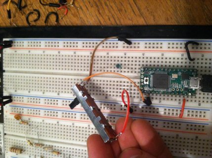
however - my fader connection is fairly flimsy - cant seem to get it directly into breadboard

photo.jpg

haha so i guess now my question - whats a good way to get a fader securely into a breadboard?
 
Connect the pot to AGND, not normal GND. Connect the capacitor from the signal to AGND too.

There are 2 downsides to larger capacitors. First, a capacitor together with the pot's resistance will delay the response. The delay is approx 2.5 * R * C, where R is the pot's resistance (in ohms) and C is the capacitance (in farads). For a 0.1 uF capacitor, that's 2.5 * 10e3 * 0.1e-6, which works out to be about 2.5 ms. For humans, delays under 10 ms to 50 ms usually aren't perceivable, so 2.5 ms is probably fine. But stepping up to a 470 uF capacitor would add a very noticeable lag.

The other issue with capacitors is they're not all created equal when it comes to high frequency response. Ceramic types are much better than aluminum. Fortunately, pretty much all modern 0.1 uF capacitors will be ceramic. Among ceramic, NP0 are the best, but you probably won't find any 0.1 uF that are NP0 rated. X7R or X5R are fine too, for this use. Y5V are lower quality, but might be ok too. Never use Z5U, which are of such low quality to be only useful for disposable items.

Rarely does soldering vs solderless breadboard construction matter. However, if you are in an area with a lot of lower frequency radio interference, the distance between the signal wire and ground wire can matter. A really good strategy for that pot in the photo would be to run the signal wire long the bottom side of the pot and then loosely twist it around the signal wire (a longer ground wire or shorter signal wire might be needed) until they both reach the Teensy, with each wire going its own direction only as far as needed to get to the A0 and AGND pins.
 
Ya, I typo'd the 470 uF . . . was meant to read 470 nF . . . uF would be way too laggy. On the other hand, it's worth playing with the damping effect you get with the caps (noise aside) to help a light, cheap fader feel like it's something a little more substantial.

I think AGND will likely solve your problems - but I also noticed you have the 3.3V rails and GND rails hooked up to both power bus strips on your board. If you don't need to distribute power like that, don't do it - the combined length of the two busses + jumper wire is going to be an effective little antenna. You may want to decouple the 3.3V line to GND with a 0.1uF and 1uF in parallel, possibly a 10uF as well (the reason for the parallel caps is to expand the effective frequency filtering range), especially if you have other noisy components on the 3.3V rail.
 
great - thanks!

A really good strategy for that pot in the photo would be to run the signal wire long the bottom side of the pot and then loosely twist it around the signal wire (a longer ground wire or shorter signal wire might be needed) until they both reach the Teensy, with each wire going its own direction only as far as needed to get to the A0 and AGND pins.

did you mean to say to twist the signal wire around the ground wire?
 
You may want to decouple the 3.3V line to GND with a 0.1uF and 1uF in parallel, possibly a 10uF as well (the reason for the parallel caps is to expand the effective frequency filtering range), especially if you have other noisy components on the 3.3V rail.

I have seen this suggested a few times in multiple sources and am confused by it. Don't capacitors only work as a filter where current is flowing in both directions? I understand how they work in the context of an AC waveform for example - by taking a little bit longer than normal and therefore unable to process higher frequencies - but I can't quite grasp there function in a DC power supply when current is only going to flow through it once...
 
Did you try using AGND rather than GND for the pot/fader (connected directly to the AGND pin rather than through a bus)?
 
I have seen this suggested a few times in multiple sources and am confused by it. Don't capacitors only work as a filter where current is flowing in both directions? I understand how they work in the context of an AC waveform for example - by taking a little bit longer than normal and therefore unable to process higher frequencies - but I can't quite grasp there function in a DC power supply when current is only going to flow through it once...

The noise you are trying to get rid of is not DC, it is an AC waveform. At DC, a capacitor is an open circuit.
 
that is, "noise" cannot be "DC" (unchanging). On a power supply, often there is noise superimposed (summed) on DC.
 
Status
Not open for further replies.
Back
Top