Hello!
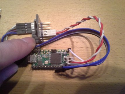
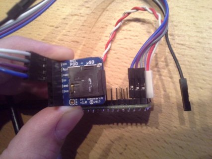
I want to use a microSD card on a Teensy3.1 so bought a microSD breakout board from Ciseco, because it is simple, small and cheap. A datasheet can be found here. I connected the boards using the supplied 10cm wires for digital pins and some other wires of about the same length for power/gnd like this:
teensy:
I used the example SDInfo from sdfatlib 20131225 and cardinfo from Arduino SD lib to test and both fail in the very first initialization step with error 0x1 (data 0xff). According to docs/output this means that no card seems to respond/be found. I used a NoName 2GB card and a Samsung 32GB SDHC card. Both produce the same output.
To find the problem I did the following steps:
1. Placed some debug output (Serial.print...) in sdfatlib to check if the right SPI code is used and where the problem arises. Everything seems to be allright but no answer comes in. I increased waiting time without success. SPI freq is set to lowest value by default in this stage of initialization, so reducing SPI_XXX_SPEED makes no difference here.
2. Used a multimeter to check if the breakout board has any pins shorted to another. Wanted to check connection of microSD socket to board but can't reach the pins of the socket because they are in/under the socket. Only did a visual check and the solder points look OK.
3. Used my fathers old scope (maybe from the 80s?) to try to get a better insight in what is happening. First of all I am new to scopes and found out that the scope shows a signal that seems to be the 50Hz from the socket, when not connected to something.
I checked the SPI clock and found it in the low 3digit kHz range I think. The flanks start sharply and are rounded in the last quarter both on the rising and the falling flank. The rounding is not to bad so there's still a distinct plateau.
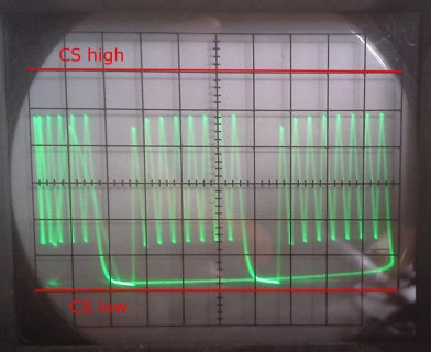
Next I tried to check the CS signal and found sth. that I don't understand. The signal is in the middle of the scopes display in the beginning, it falls for an extremely short amount of time in the beginning of the initialization but instantly comes back to the center for the waiting time an rises for an equally short amount of time in the end. I don't understand what's happening here and can only guess that the scope pulls the line to a "medium"? level. This behaviour stayed the same on other pins that I configured for CS.
In the end I tried to check the data pins MISO/MOSI but didn't find much. I synced the scope to SPI CLK but found the signal to be totally weird. Additionally I think I influenced the MISO signal with the scope because the error data reported by SDInfo changed to 0x0 (error code stayed 0x1).
4. In the end I connected my 5110 LCD to pins 8-12 to check if the pins are defective but found no problem.
Now I'm at the end of my knowledge. Every hint what I did wrong or could check next is very welcome. The only thing that came to my mind is buying a microSD sniffer board to check the soldering of the socked to the board but would rather do anything that can be done without buying stuff first.
Thanks for reading this!
I want to use a microSD card on a Teensy3.1 so bought a microSD breakout board from Ciseco, because it is simple, small and cheap. A datasheet can be found here. I connected the boards using the supplied 10cm wires for digital pins and some other wires of about the same length for power/gnd like this:
teensy:
| Teensy pin no. | Teensy pin name | I/O POD pin name |
| - | GND (near button) | GND |
| - | 3.3V (near button) | 3V3 |
| 10 | CS | SS |
| 11 | DOUT | MOSI |
| 12 | DIN | MISO |
| 13 | SCK | SCK |
I used the example SDInfo from sdfatlib 20131225 and cardinfo from Arduino SD lib to test and both fail in the very first initialization step with error 0x1 (data 0xff). According to docs/output this means that no card seems to respond/be found. I used a NoName 2GB card and a Samsung 32GB SDHC card. Both produce the same output.
To find the problem I did the following steps:
1. Placed some debug output (Serial.print...) in sdfatlib to check if the right SPI code is used and where the problem arises. Everything seems to be allright but no answer comes in. I increased waiting time without success. SPI freq is set to lowest value by default in this stage of initialization, so reducing SPI_XXX_SPEED makes no difference here.
2. Used a multimeter to check if the breakout board has any pins shorted to another. Wanted to check connection of microSD socket to board but can't reach the pins of the socket because they are in/under the socket. Only did a visual check and the solder points look OK.
3. Used my fathers old scope (maybe from the 80s?) to try to get a better insight in what is happening. First of all I am new to scopes and found out that the scope shows a signal that seems to be the 50Hz from the socket, when not connected to something.
I checked the SPI clock and found it in the low 3digit kHz range I think. The flanks start sharply and are rounded in the last quarter both on the rising and the falling flank. The rounding is not to bad so there's still a distinct plateau.
Next I tried to check the CS signal and found sth. that I don't understand. The signal is in the middle of the scopes display in the beginning, it falls for an extremely short amount of time in the beginning of the initialization but instantly comes back to the center for the waiting time an rises for an equally short amount of time in the end. I don't understand what's happening here and can only guess that the scope pulls the line to a "medium"? level. This behaviour stayed the same on other pins that I configured for CS.
In the end I tried to check the data pins MISO/MOSI but didn't find much. I synced the scope to SPI CLK but found the signal to be totally weird. Additionally I think I influenced the MISO signal with the scope because the error data reported by SDInfo changed to 0x0 (error code stayed 0x1).
4. In the end I connected my 5110 LCD to pins 8-12 to check if the pins are defective but found no problem.
Now I'm at the end of my knowledge. Every hint what I did wrong or could check next is very welcome. The only thing that came to my mind is buying a microSD sniffer board to check the soldering of the socked to the board but would rather do anything that can be done without buying stuff first.
Thanks for reading this!


