Mosfet to influence resistance

Status
Not open for further replies.

jakorten

Well-known member
I have a situation where I need to lower the resistance:

--- [ 10 ohm ] ---

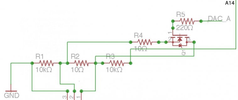
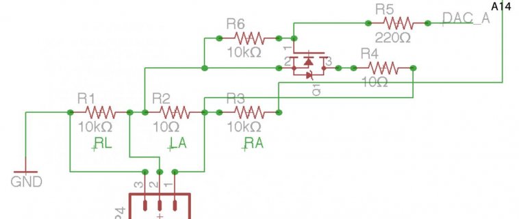
Total situation is this: GND --L1-- [ 10 k ] --L2-- [ 10 ohm ] --L3 -- [10 k] --- A14 of Teensy 3.1

The basics of the circuit (lower part from the image and as explained above), work very well. But now the next thing.

The 10 ohm resistor part should (now and then) become 5 ohm instead of ten ohm. Tests with another 10 ohm resistor parallel to the current 10 ohm resistor show that this works very well.


But... how do I switch a 10 ohm resistor parallel to the current one?!

I was thinking about a N-channel MOSFET

mosfet_switch.jpg

First of all, would this work? Then, how do I choose proper values for the MOSFET?

Rds ON is important in my case: I of course want it to be lower than 10 ohm.
But the gate source voltage is also important isn't it?

If I correctly interpret this: http://www.electronics-tutorials.ws/transistor/tran_7.html
I guess it should be less than 3V or so?!!

This might be a good candidate: http://nl.mouser.com/ProductDetail/...=sGAEpiMZZMshyDBzk1/Wi3ROP6NWFBlWNC6dc0MzOG0= I think.

My concern with my circuit is that since I am not able to connect the Drain directly to 3.3V or otherwise the Source to GND, that it won't work.

B.t.w. I want to feed the MOSFET with a DAC, although I don't know if that is still needed.

I'm thinking that this might be a better option, but also with mosfets so maybe the same problem?! 5 ohms, so at least low enough: http://www.mouser.com/ds/2/427/vo1400ae-244774.pdf
 

Attachments

  • mosfet_switch.jpg
    mosfet_switch.jpg
    39.7 KB · Views: 311
Last edited:
If you don't need this to change quickly (from 10 to 5 and back to 10 ohms), I'd use a reed relay. They have very low on resistance and they last a very long time. Reed relays may seem "low tech", but they are very commonly used in signal generators, oscilloscopes and other instrumentation. This sounds exactly like the type of signal generation application where reed relays are normally used.

You'll probably need a NPN or other transistor to turn on the relay coil. Like all inductive loads, always put a reverse-bias diode in parallel with the coil, to prevent a high voltage spike when you turn off the current. If you forget this, damage to the transistor and even Teensy are likely. Some reed relays have the diode built in.

If you need the output to change rapidly, perhaps a reed relay would be too slow?

In that case, I'd use a mosfet. You didn't say what you're doing with A14, but I'm guessing you're using as a DAC output and these resistors divide the voltage, so you get a very tiny signal.

I see at least 2 problems with a mosfet.

#1: The source might be anywhere from 0 to 1.6 volts, so you'll probably have to apply more than 3.3V to the gate. For example, that SQ3426 part requires 4.5V to get 0.063 ohms on resistance, which means you'll need to apply at least 6.1 volts if the source is at 1.6 volts. Probably the simplest way to get a gate drive voltage is switched capacitors.

#2: When you switch the gate voltage, it will AC couple to the output. Mosfets are basically a capacitor (although not a very linear one) from gate to source. At the source terminal, you've got a 10K resistor to ground and 10.01K to the A14/DAC pin, which probably has an equivalent output impedance of about 500 ohms (really, just a wild guess on my part, since Freescale doesn't spec this). So the gate-source capacitor and approx 5K impedance to DC will form a high-pass filter from your control signal to the output pin.

I'd try using a RS-232 level converter, like a MAX232 or MAX3232, to create the gate control voltage. Those parts make creating such voltages easy, with just 1 chip and a few capacitors. They also usually have slew-rate limiting on their output pins, which will limit the high frequencies present as it changes. Some will still couple to the output, but at least that might help.

You also mentioned "I want to feed the MOSFET with a DAC, although I don't know if that is still needed". Maybe you're intending to actually control the mosfet's on-resistance, rather than just go from off to approx 0.06 ohm? Maybe there's some other reason for this? Without understanding *why* you want to do such a thing, it's really impossible to comment much. But whatever the reason, those 2 issues will likely come into play, on top of all the difficult issues of using mosfets as linear devices (eg, bias points are temperature dependent and vary considerably between devices, so usually some sort of opamp sensing and automatic adjustment is used).
 
Hi Paul, we use this for the ECG simulation project. That is why we use the strange 10k - 10 ohm - 10k construction. To generate a signal for respiration on a patient monitor there are basically two options:

a. put it in the ECG itself, that is very difficult
b. change the resistance of the 10 ohm part

So we would like to use the b strategy and only if we have no other option use option a. Yesterday I did a test using only the A14 DAC - 10k - 10 ohm - 10k - GND part. If I quickly connect a resistor of 10 ohm over (so parallel to) the current one I pretty much get the desired effect. We thought it would be possible to use a DAC and an optocoupler to control the 10 ohm part, but that is impossible only already because I did look look well enough and the current octocoupler has a resistance of 130 ohm at max LED input.

So would a solid state relay also work?!
http://www.mouser.com/ds/2/427/vo1400ae-244774.pdf

Or is it so much like a mosfet that one would get the same problems?!

This is then my proposed solution:
ssd_reed_option.jpg
 

Attachments

  • mosfet_switch.jpg
    mosfet_switch.jpg
    43.8 KB · Views: 217
Last edited:
Rather than try to create two 10 Ω in parallel, could you increase the 10k resistors ?

e.g. instead of having 10k..10ohm..10k, and putting another 10ohm in parallel, start with

20k..10ohm..20k

and switch another 20k in parallel with each 20k ?

For the lower 20k (the one connected to GND), you could possibly use a Teensy's digital output in open-drain mode (don't remember exactly the direct way to do this, but switching it from an INPUT (i.e. off) to an output LOW would work). Then just use nearly any FET across the upper 20k.

Note that if the DAC goes higher than the threshold of the FET (~ 1-2 V), an n-channel FET won't turn on. You could use a p-channel in parallel also (and drive its gate low when the n-ch gate is high etc.). Alternatively use a CMOS transmission gate IC (which does the same thing); these are sometimes called analog switches. Something like SN74LVC2G66 would be a place to start.
 
That would have been great indeed, but the patient monitor doesn't like that. Remember that it is meant for human beings and their resistance will also not become twice as large I guess.

A CMOS transmission gate IC, well, that is also a good idea, will try to figure that one out! What about my solid state relay idea?!
 
we use this for the ECG simulation project. That is why we use the strange 10k - 10 ohm - 10k construction.

Ok, I believe I understand why you're using 10K - 10 ohms - 10K, to create a tiny signal with voltage offset, presumably because that's the type of signal the ECG normally receives.

But I still have no understanding of why you're changing the 10 ohm resistor to 5 ohms.

I'm simply not very familiar with ECG signals and applications. But I do know analog circuits! If you explain why and what you're really trying to accomplish, but I and others here might have some ideas of alternate ways to better achieve your goals. Perhaps a creative opamp circuit could somehow do what you need.... if only I understood better what you really need?
 
Last edited:
That would have been great indeed, but the patient monitor doesn't like that. Remember that it is meant for human beings and their resistance will also not become twice as large I guess.

A CMOS transmission gate IC, well, that is also a good idea, will try to figure that one out! What about my solid state relay idea?!

in principle the SSR would work, but that particular one has 5 ohm on resistance -- not so good for your circuit. I don't think optical ones are available in much lower resistance, and if they are, then you need to be slightly concerned about leakage current. A reed relay would be better (but larger, noisier, and not directly driveable from Teensy).

Are you really just trying to generate a small voltage (DAC / 2000 ?), with some offset from GND ? To beable to help you more, you need to describe the signals you are trying to generate. This might include voltage levels, rate of change (frequency of change), accuracy, resolution, impedance level (drive strength) and many more attributes.
 
My guess is this signal could be created much better using an opamp circuit, where a 74HC4066 style analog switch adds another resistor into the feedback path to change the gain.

Or perhaps even that isn't really necessary. If 11 bits is sufficient resolution, perhaps just using different DAC output numbers in the code could be used to create the half-size signal. An opamp circuit could easily do the 1/1000 attenuation while adding a fixed offset voltage.
 
5 ohm would be enough, I could even add a 5 ohm resistor to make it equal with the 10 ohm resistor (in my test I put a second 10 ohm resistor over the first one so the total resistance will be 5 ohm and that works well), apparently making it too low influences the ECG signal too much.

@Paul, that would also be very interesting option to evaluate (the 74HC4066 construction). What we try to achieve is a respiration pattern. In simulation it almost always is like a flattened sinus (not the cardiac sinus, the mathematical one), but in real life it is much more up and down. I think I might not even need the second DAC at all.

Problem is that patient monitor companies sit on their monitors like hens (or swans) on their eggs and don't let anyone in on their 'secrets' (although I have someone in one of the companies that is helping us out a bit ;)). For a second project we might also take a different approach of course, bet we also want to keep it as simple as possible at this moment (I'm coaching two high school students on this project).

B.t.w. our school has a really bad carpet, I blew up a Teensy 3.1 two days ago by static electricity :( (fortunately school pays ;), keeps Robin too busy though I'm afraid).
 
Last edited:
I *still* have absolutely no idea why you're trying to change from 10 to 5 ohms while the project is running.

Opamps and analog circuits I know pretty well, but I'm not familiar at all with respiration patterns. I know you're trying to explain, but if you want better circuitry help, you really need to take a step back and explain what type of electrical signal you're trying to generate in a context that can be understood without specialized knowledge of physiology.
 
5 ohm would be enough, I could even add a 5 ohm resistor to make it equal with the 10 ohm resistor (in my test I put a second 10 ohm resistor over the first one so the total resistance will be 5 ohm and that works well), apparently making it too low influences the ECG signal too much.

No, using the SSR alone across the 10 ohm won't work well. The 5 ohm on-resistance is the 'worst case' value -- typical parts will be much (perhaps 2x ?) better, and the value will vary significantly with input signal strength (LED illumination), and temperature. If you can tolerate a > 50 % change in your signal, it might work though.

2nd, actually the 74HC4066 may not be a good choice -- its resistance is not specified at 3.3 V (the voltage that Teensy uses) - it's spec'ed to 4.5 V; there is very limited info about 2 V operation. The SN74LVC2G66 will work well down to a supply of 1.65 V.
 
Probably pictures say more than words: https://www.youtube.com/watch?v=tBSMgcFLr_8

it was actually meant for one of my (Dutch) students so comments in Dutch, it is still an ugly ECG (we have much better ones but that doesn't really matter for this test. The lower line (yellow) with RR next to it is flat, until I short the 10 ohm with another 10 ohm resistor: that results in an RR signal. One will need to let it fall together with the heart rhythm R-top if possible to avoid flutter in the ECG pattern.

Although the SN74LVC2G66 is an interesting idea, I think there are even better counterparts:
http://www.mouser.com/Semiconductor...witch-ICs/_/N-7590c/?Ns=On Resistance - Max|0

This seems to be a good option?!: TS3A24159YZPR
ON-state resistance 0.34 Ohms
1.65-V to 3.6-V Single-Supply Operation
 
Last edited:
Status
Not open for further replies.
Back
Top