ADC library, with support for Teensy 4, 3.x, and LC

Update: Now it works with the Audio library:
Teensy 3.0 is compatible, except if you try to use the Audio library ADC input (AudioInputAnalog), because there's only one ADC module so you can't use it for two things.
Teensy 3.1 is compatible. If you want to use AudioInputAnalog and the ADC you have to use the ADC_1 module, the Audio library uses ADC_0. Any calls to functions that use ADC_0 will most likely crash the program. Note: make sure that you're using pins that ADC_1 can read (see pictures above)! Otherwise the library will try to use ADC_0 and it won't work!!

Pedvide, this works fantastic! I numbers I get from my log scale light sensor are much more stable. Your library is certainly advanced but the more I read, I realized it is incredibly well documented! Thank you!

I found this image helpful for those trying to figure out which pins are on ADC0, ADC1, or both!
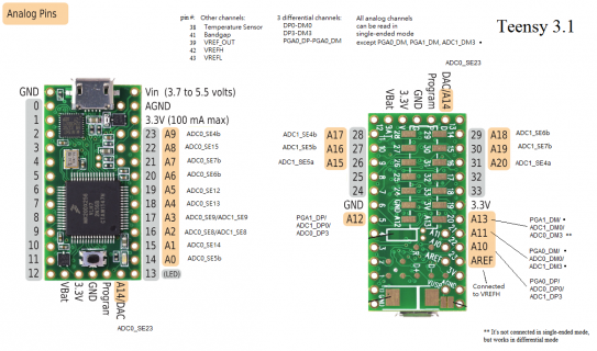
Teensy3_1_AnalogCard.png
I have a jumper to cut and solder to change my mic pin, but this edit gets my two earlier prototypes running with ADC+Audio libraries!

Also, I went ahead and cleaned up the example code below. It's based on PRJC's FFT example but configured for taking audio from a mic without the Audio Board and taking an analog reading from ADC1 which currently isn't used by InputAudioAnalog. New Users: currently AnalogReference(INTERNAL) is currently hard coded into the library, depending on you wiring/mic you may need to edit the library. See: https://github.com/PaulStoffregen/Audio/issues/89
Important note from Paul on the topic:
I had originally intended to include an adc1.analogReference() function, like the DAC object has. Somehow, this never happened. It'll come in some future version. Pull requests are welcome.... (hint, hint)

However, changing the reference to 3.3V will reduce the signal amplitude by 3. For hardware where the signal is already very low, you might be better off using the recommended circuit. Those 2 extra capacitors and 4 resistors will buy your 3X the signal gain.

Code:
// FFT Test for Analog Mic
//
// Use PRJC's Audio library to compute audio spectrum analysis 
// from an analog mic input on ADC0 while taking an analog read 
// sample from a pin on ADC1 using Pedvide's ADC library. 
// Download the latest copy at:
// https://github.com/pedvide/ADC
//
// Compute a 1024 point Fast Fourier Transform (spectrum analysis)
// on audio connected to the Left Line-In pin.  By changing code,
// a synthetic sine wave can be input instead.
//
// The first 40 (of 512) frequency analysis bins are printed to
// the Arduino Serial Monitor.  Viewing the raw data can help you
// understand how the FFT works and what results to expect when
// using the data to control LEDs, motors, or other fun things!
//
// This example code is in the public domain. 


#include <Audio.h>
#include <Wire.h>
#include <SPI.h>
#include <SD.h>

#include <ADC.h>

// CREATE THE ADC OBJECT FIRST, BEFORE ALL AUDIO STUFF!!
ADC *adc = new ADC(); // adc object
const int readPin = 30; // ADC1, Choose a pin the can be accessed by the ADC *NOT* being used to stream audio.
                        // Currently this must be a pin on ADC1, but has been suggested as a fix for the audio library.

// Create the Audio components.  These should be created in the
// order data flows, inputs/sources -> processing -> outputs
// Using adafruit mic-amp, edit library to turn-off internal voltage reference in 
// inputAnalog.cpp 

AudioInputAnalog       analogAudioIn(15); //Pin 15, mic pin, currently must be on ADC0
AudioSynthWaveformSine sinewave;
AudioAnalyzeFFT1024    myFFT;


// Connect either the live input or synthesized sine wave
AudioConnection patchCord1(analogAudioIn, 0, myFFT, 0);
//AudioConnection patchCord1(sinewave, 0, myFFT, 0);


void setup() {
  // Audio connections require memory to work.  For more
  // detailed information, see the MemoryAndCpuUsage example
  AudioMemory(12);


  // Configure the window algorithm to use
  //myFFT.windowFunction(AudioWindowHanning1024);
  myFFT.windowFunction(NULL);

  // Create a synthetic sine wave, for testing
  // To use this, edit the connections above
  sinewave.amplitude(0.8);
  sinewave.frequency(1034.007);


  adc->setAveraging(8, ADC_1); // set number of averages
  adc->setResolution(12, ADC_1); // set bits of resolution
  adc->setConversionSpeed(ADC_VERY_LOW_SPEED, ADC_1); // change the conversion speed
  adc->setSamplingSpeed(ADC_VERY_LOW_SPEED, ADC_1); // change the sampling speed

}

int value = 0;

void loop() {
  float n;
  int i;

  value = adc->analogRead(readPin, ADC_1); // read a new value, will return ADC_ERROR_VALUE if the comparison is false.

  if (myFFT.available()) {
    // each time new FFT data is available
    // print it all to the Arduino Serial Monitor
    //Serial.print("T: "); //Testing touchRead
    //Serial.print(touchRead(0));
    Serial.print("Pin: ");
    Serial.print(readPin);
    Serial.print(" = ");
    Serial.print(value*3.3/adc->getMaxValue(ADC_1), DEC); //assuming 3.3v reference voltage
    Serial.print("v   FFT: ");
    for (i=0; i<40; i++) {
      n = myFFT.read(i);
      if (n >= 0.008) {
        Serial.print(n);
        Serial.print(" ");
      } 
      else {
        Serial.print("  -  "); // don't print "0.00"
      }
    }
    Serial.print("\n"); 
  }
}

I've learned a lot from this issue! Thanks to everyone who helped!
 
I'm having issues with ringBufferDMA
It only seems to be recording to the first 4 values.

Here's the output I get after sending "sccccccccp" I have a pot connected to the input pin around 3300.
Code:
Start DMA
Conversion: 
ADC0_ISR
DMA_CH2_ISR
Conversion: 
ADC0_ISR
DMA_CH2_ISR
Conversion: 
ADC0_ISR
DMA_CH2_ISR
Conversion: 
ADC0_ISR
DMA_CH2_ISR
Conversion: 
ADC0_ISR
DMA_CH2_ISR
Conversion: 
ADC0_ISR
DMA_CH2_ISR
Conversion: 
ADC0_ISR
DMA_CH2_ISR
Conversion: 
ADC0_ISR
DMA_CH2_ISR
Buffer: Address, Value
1FFF9388, 3308
1FFF938A, 3306
1FFF938C, 3310
1FFF938E, 3311
1FFF9390, 10236
1FFF9392, -30318
1FFF9394, -18379
1FFF9396, -32235

Subsequent reads only write over the first 4. That data only changes when I unplug and reconnect the Teensy.
I've tried it with the interrupt off with the same results.
I'm using Arduino 1.0.6 and Teesny 1.20 with a 3.1.

Thanks!
 
Last edited:
I'll have a look at it. The DMA part will benefit from all the additions to the Teensy core.
What's happening is that the buffer should start at an address ending in 0, but it's not. When it reaches the address 1FFF938E it wraps around to 1FFF9380 (probably).
 
I'll have a look at it. The DMA part will benefit from all the additions to the Teensy core.
What's happening is that the buffer should start at an address ending in 0, but it's not. When it reaches the address 1FFF938E it wraps around to 1FFF9380 (probably).

I've been looking into this as I was suffering from this as well. It did seem to come and go, but I did find a few weird things in the library code:
1. Line 161 of RingBufferDMA.cpp
return (p + 1)&(2*b_size-1);
I believe that that 2 should not be there, i.e the line should read
return (p + 1)&(b_size-1);

2. When that is fixed you can drop the extra test against b_start at line 154 so that it can read
int result = elems[b_start];

3. I've been trying to play with the value of DMA_BUFFER_SIZE to increase it to at least 64 which I need to try and improve Serial.write to increase sampling rate in my code (currently limited to 67KHz). Seems that it does not work with any value about 8. I don't know enough arduino low level code to figure out what is wrong, only hint is in the comment on line 92
src and dst data is 16 bit (2 bytes), buffer size 2^^4 bytes = 8 values

Is there a way to increase the buffer size?

Thanks
 
Having some fun with the library. Im reading 6 different analog pins in sequence using synchronized reads and repeating 16 times.
Averaging 1 sync read every 11us or 5.5uS per pin @ 48MHz and 8.6us or 4.3uS per pin @ 72MHz.

Here is the code, im sure its hard on the eyes for you coding pros...


Code:
#include <ADC.h>

const int readPin = A0;    //Throttle
const int readPin2 = A18;  //Current
const int readPin3 = A1;   //BusV
const int readPin4 = A19;  //BattV
const int readPin5 = A2;   //MotorTemp
const int readPin6 = A20;  //HS-Temp

ADC *adc = new ADC(); // adc object


void setup() {

    pinMode(LED_BUILTIN, OUTPUT);
    pinMode(readPin, INPUT);
    pinMode(readPin2, INPUT);
    pinMode(readPin3, INPUT);
    pinMode(readPin4, INPUT);
    pinMode(readPin5, INPUT);
    pinMode(readPin6, INPUT);


    Serial.begin(9600);

    ///// ADC0 ////
    //adc->setReference(ADC_REF_INTERNAL, ADC_0); change all 3.3 to 1.2 if you change the reference

    adc->setAveraging(1); // set number of averages
    adc->setResolution(12); // set bits of resolution

    // it can be ADC_VERY_LOW_SPEED, ADC_LOW_SPEED, ADC_MED_SPEED, ADC_HIGH_SPEED_16BITS, ADC_HIGH_SPEED or ADC_VERY_HIGH_SPEED
    // see the documentation for more information
    adc->setConversionSpeed(ADC_HIGH_SPEED); // change the conversion speed
    // it can be ADC_VERY_LOW_SPEED, ADC_LOW_SPEED, ADC_MED_SPEED, ADC_HIGH_SPEED or ADC_VERY_HIGH_SPEED
    adc->setSamplingSpeed(ADC_HIGH_SPEED); // change the sampling speed

    // always call the compare functions after changing the resolution!
    //adc->enableCompare(1.0/3.3*adc->getMaxValue(ADC_0), 0, ADC_0); // measurement will be ready if value < 1.0V
    //adc->enableCompareRange(1.0*adc->getMaxValue(ADC_0)/3.3, 2.0*adc->getMaxValue(ADC_0)/3.3, 0, 1, ADC_0); // ready if value lies out of [1.0,2.0] V

    ////// ADC1 /////
    adc->setAveraging(1, ADC_1); // set number of averages
    adc->setResolution(12, ADC_1); // set bits of resolution
    adc->setConversionSpeed(ADC_HIGH_SPEED, ADC_1); // change the conversion speed
    adc->setSamplingSpeed(ADC_HIGH_SPEED, ADC_1); // change the sampling speed

    // always call the compare functions after changing the resolution!
    //adc->enableCompare(1.0/3.3*adc->getMaxValue(ADC_1), 0, ADC_1); // measurement will be ready if value < 1.0V
    //adc->enableCompareRange(1.0*adc->getMaxValue(ADC_1)/3.3, 2.0*adc->getMaxValue(ADC_1)/3.3, 0, 1, ADC_1); // ready if value lies out of [1.0,2.0] V


    delay(500);
    Serial.println("end setup");
}

int value[16] = {0};
int value2[16] = {0};
int value3[16] = {0};
int value4[16] = {0};
int value5[16] = {0};
int value6[16] = {0};
int testtime;

ADC::Sync_result result;

void loop() {
  
int i;

elapsedMicros sinceStart; // start the clock

for (i = 0; i < 16; i++) {
    result = adc->analogSynchronizedRead(readPin, readPin2);
    value[i] = result.result_adc0;
    value2[i] = result.result_adc1;
    result = adc->analogSynchronizedRead(readPin3, readPin4);
    value3[i] = result.result_adc0;
    value4[i] = result.result_adc1;
    result = adc->analogSynchronizedRead(readPin5, readPin6);
    value5[i] = result.result_adc0;
    value6[i] = result.result_adc1;

}

testtime = sinceStart;   //how long it took to read all 6 pins 16 times.
Serial.print("Full read time was ");
Serial.print(testtime);
Serial.println(" us");

//First ADC array                        
    Serial.print("Pin: ");   //Copy and paste hell from here on out...
    Serial.print(readPin);
    Serial.print(", value ADC0: ");

for (i = 0; i < 16; i++) {
    Serial.print(value[i]*3.3/adc->getMaxValue(ADC_0), DEC);
        Serial.print(" ");  
}

//Second ADC array
    Serial.println(" ");
    Serial.print("Pin: ");   //Copy and paste hell from here on out...
    Serial.print(readPin2);
    Serial.print(", value ADC1: ");

for (i = 0; i < 16; i++) {
    Serial.print(value2[i]*3.3/adc->getMaxValue(ADC_1), DEC);  
        Serial.print(" ");
}

//Third ADC array
    Serial.println(" ");
    Serial.print("Pin: ");   //Copy and paste hell from here on out...
    Serial.print(readPin3);
    Serial.print(", value ADC0: ");

for (i = 0; i < 16; i++) {
    Serial.print(value3[i]*3.3/adc->getMaxValue(ADC_0), DEC);
        Serial.print(" ");  
}

//Forth ADC array
    Serial.println(" ");
    Serial.print("Pin: ");   //Copy and paste hell from here on out...
    Serial.print(readPin4);
    Serial.print(", value ADC1: ");

for (i = 0; i < 16; i++) {
    Serial.print(value4[i]*3.3/adc->getMaxValue(ADC_1), DEC);
      Serial.print(" ");  
}

//Fifth ADC array
    Serial.println(" ");
    Serial.print("Pin: ");   //Copy and paste hell from here on out...
    Serial.print(readPin5);
    Serial.print(", value ADC0: ");

for (i = 0; i < 16; i++) {
    Serial.print(value5[i]*3.3/adc->getMaxValue(ADC_0), DEC);
      Serial.print(" ");  
}

//Sixth ADC array
    Serial.println(" ");
    Serial.print("Pin: ");   //Copy and paste hell from here on out...
    Serial.print(readPin6);
    Serial.print(", value ADC1: ");

for (i = 0; i < 16; i++) {
    Serial.print(value6[i]*3.3/adc->getMaxValue(ADC_1), DEC);
      Serial.print(" ");  
}


  delay(1000);
}

And a few snips from my serial monitor.
DMM values are
Pin 14: 3.072V
Pin 29: 2.047V
Pin 15: 1.699V
Pin 30: 2.349V
Pin 16: 0.783V
Pin 31: 2.683V

Code:
6 channels in arrays @ 48MHz
Full read time was 522 us
Pin: 14, value ADC0: 3.0775824 3.0759706 3.0759706 3.0775824 3.0767765 3.0767765 3.0767765 3.0767765 3.0759706 3.1041758 3.0630769 3.0759706 3.0711355 3.0743589 3.0767765 3.0695238  
Pin: 29, value ADC1: 2.0541391 2.0541391 2.0541391 2.0557509 2.0565567 2.0549450 2.0549450 2.0557509 2.0541391 2.0533333 2.0581684 2.0557509 2.0541391 2.0613919 2.0557509 2.0533333  
Pin: 15, value ADC0: 1.7027838 1.7060073 1.7060073 1.7052014 1.6979487 1.7052014 1.7060073 1.7043956 1.7060073 1.7060073 1.7060073 1.7084249 1.7060073 1.7043956 1.7060073 1.7060073  
Pin: 30, value ADC1: 2.3539194 2.3555311 2.3555311 2.3547252 2.3563369 2.3434432 2.3539194 2.3547252 2.3563369 2.3555311 2.3547252 2.3563369 2.3555311 2.3547252 2.3571428 2.3555311  
Pin: 16, value ADC0: 0.7736263 0.7913553 0.7744322 0.7913553 0.7905494 0.7752380 0.7736263 0.7945787 0.7744322 0.7905494 0.7800732 0.7921611 0.7897435 0.7736263 0.7921611 0.7752380  
Pin: 31, value ADC1: 2.6883516 2.6883516 2.6891575 2.6891575 2.6891575 2.6883516 2.6891575 2.6956043 2.6859340 2.6875457 2.6907692 2.6988278 2.6907692 2.6899633 2.6915750 2.6891575

Code:
6 channels in arrays @ 72MHz
Full read time was 411 us
Pin: 14, value ADC0: 3.0743589 3.0759706 3.0783882 3.0767765 3.0783882 3.0783882 3.0783882 3.0759706 3.0783882 3.0783882 3.0767765 3.0759706 3.0824175 3.0791941 3.0783882 3.0735531  
Pin: 29, value ADC1: 2.0525274 2.0541391 2.0549450 2.0541391 2.0533333 2.0533333 2.0549450 2.0557509 2.0541391 2.0549450 2.0549450 2.0557509 2.0533333 2.0493040 2.0509157 2.0589743  
Pin: 15, value ADC0: 1.7035897 1.7052014 1.7060073 1.7068131 1.7068131 1.7084249 1.7076190 1.7068131 1.7068131 1.7076190 1.7068131 1.7132600 1.7068131 1.7084249 1.7011721 1.7172893  
Pin: 30, value ADC1: 2.3539194 2.3555311 2.3571428 2.3571428 2.3571428 2.3579487 2.3579487 2.3579487 2.3579487 2.3571428 2.3571428 2.3619780 2.3531135 2.3660073 2.3595604 2.3571428  
Pin: 16, value ADC0: 0.7832967 0.7849084 0.7849084 0.7849084 0.7849084 0.7857142 0.7849084 0.7849084 0.7849084 0.7849084 0.7849084 0.7816849 0.7760439 0.7816849 0.7784615 0.7841025  
Pin: 31, value ADC1: 2.6867399 2.6883516 2.6899633 2.6899633 2.6899633 2.6907692 2.6899633 2.6907692 2.6907692 2.6915750 2.6907692 2.6915750 2.6915750 2.6778754 2.6867399 2.6899633

I may make a none synchronized version to see if its slower or faster.
 
Last edited:
laughingrice,
thanks for the suggestions, now I'm working hard on USB Host mode, so I'm not sure when I'll be able to test this.
About changing the buffer size, you have to change the DMA buffer size too! In line 90 change DMA_TCD_ATTR_DMOD(4); to other sizes. The implementation of the circular buffer only works with sizes that are powers of 2.

Donziboy2,
Your code looks good! Something else you can try is to do the 16 reads on the same pair of pins consecutively, then an other 16 reads of the other 2 pins, etc. See if there's a difference in speed and/or accuracy.
 
Donziboy2,
Your code looks good! Something else you can try is to do the 16 reads on the same pair of pins consecutively, then an other 16 reads of the other 2 pins, etc. See if there's a difference in speed and/or accuracy.

Thanks, the reason I ran them that way is I needed to see how long it takes to read a pair then switch to the next set. I want to squeeze all the speed I can get from them. I plan to sample all 6 and then average the samples over time. Im slowly working on a motor controller for a Go Cart and I want to sample the 6 apins + some dpins at 4Ksps or greater. I have been bouncing between testing small pieces of code and cramming all the components on 3 small boards that are 96.5x116.8mm that will be stacked on top of each other. All the analogs will be connected to Op-Amps so I should be able to keep the noise down and I will be averaging a good number of samples.

I have plans to run a touch screen also but it may get interesting since I think the only way to do it is send the data to another teensy and do the screen on it plus I would like to log the data also so if I run into issues I can trouble shoot it.

Hardware wise I have it mostly down, its the code that I have been neglecting:rolleyes:
 
Oddly enough increasing the clock rate to 96MHz actually increased the total read time from 411us at 72MHz to 425us....

Another odd thing I noticed that is probably more to do with the IDE is that I decided to remove the 3.3 value from "Serial.print(value3*3.3/adc->getMaxValue(ADC_0), DEC);" since I used it in multiple places and just use a single float variable which would make it easier to tune later instead of having to change it several times. When I changed my above code it ended up using close to a thousand bytes more then the original code.
 
Last edited:
I suspect when you moved the 3.3 value to a variable, you did not use the const keyword in declaring it. If you used const the compiler could do constant folding on the operation. This assumes you are coding in C++ (i.e. in the .ino/.pde file or in .cpp library files). If you are coding a library function in pure C, the rules for const are different, and the compiler has to treat it like a variable (but one it could put in read-only memory).
 
Oddly enough increasing the clock rate to 96MHz actually increased the total read time from 411us at 72MHz to 425us....

Another odd thing I noticed that is probably more to do with the IDE is that I decided to remove the 3.3 value from "Serial.print(value3*3.3/adc->getMaxValue(ADC_0), DEC);" since I used it in multiple places and just use a single float variable which would make it easier to tune later instead of having to change it several times. When I changed my above code it ended up using close to a thousand bytes more then the original code.


Because the teensy doesn't have an FPU, any work with floats is significantly slower than regular integer math. I also believe that using the float data types adds an additional file to the compilation process in order for the teensy to deal with floats, which would explain your increased compiled program size.


Edit: having said all that, you were using a decimal in your original code anyway so I might be talking rubbish.
 
Last edited:
@MichaelMeissner

I used a const and I placed it at the top of the code along with the pin constants I used.
As for using C++ I have a hard enough time with normal C :eek:


@Cosford

The reason I tried it was to get rid of the 6 times I repeated 3.3 in the code and have one value I could change once I know what my actual 3.3V power rail is at.
 
With that I mean two things:

All registers bits are changed using their bit-band addresses, so the modify instructions are atomic. This means that if you change a bit 0 in register regA (example) inside an interrupt, and in the main loop you change bit1 in regA, you can be sure that the bits will have the values you wanted.
If the library didn't use atomic access then the loop code would read the value of regA, change bit1, and write the old regA+the modified bit. The problem is that if the interrupt happens just after reading regA, but before writing it again, and the interrupt code changes bit 1, when the interrupt returns and the loop code executes it will write an old version of regA, thus reverting the changes of the interrupt.

The second point is that when you start a measurement that isn't continuous, the function checks whether the ADC is already running, if so, it stores the settings, does the reading, and then restores the ADC so it continues doing the measurement.
For example, if you have a continuous measurement in pin1 but from time to time you want to measure the voltage of pin2, you can just simply call analogRead(pin2) (from normal code or an interrupt). It will "pause" the continuous measurement, return the value of pin2 and restore the ADC so it keeps measuring pin1.
 
Anybody have the Windows base beta 1.6 ready to run that can give this compile a try - Paul's suspecting there may be a Windows anomaly.
WARNING: library Audio claims to run on [sam] architecture(s) and may be incompatible with your current board which runs on [avr] architecture(s).

For my Teensy 3.1 I'm trying to use this above code from Message #101 above on Win7 and Win8 with the current 1.6 beta and my systems are coming up AVR and not SAM and it won't compile using the Arduino libs the IDE is trying.

- which would delay important work - anyone reading this compiling it with the Beta on a Windows system? I've done what I can to disprove user error, I also can't get the included "C:\Users\Tim\Documents\Arduino\hardware\teensy\avr\libraries\Audio\examples\Analysis\FFT\FFT.ino" example to work. Closest I get is when I delete the true Arduino AVR :: "C:\Users\Tim\Documents\Arduino\libraries\Audio" - which is just grasping debuggery.
 
Paul gave this a try and it worked - Looks like I get to clean install 3 machines.

UPDATE: Above post #101 still failing on my clean 1.6 ZIP file copy.
 
Last edited:
Code from the above post #101 still results in my getting this error. If anyone else [1.6 and TeensyDuino Beta-6] [with a WINDOWS system] could confirm.:
T_ADCLibUpd_101_25532.ino:26:17: fatal error: ADC.h: No such file or directory
compilation terminated.
Error compiling.
 
Last edited:
The ADC library at https://github.com/pedvide/ADC works with Arduino 1.0.6 / Teensyduino 1.21-beta6 for Teensy 3.0, but does not compile for Teensy LC, the error is:

Code:
C:\Program Files (x86)\Arduino\libraries\ADC-master\ADC.cpp: In function 'void dma_isr_0()':
C:\Program Files (x86)\Arduino\libraries\ADC-master\ADC.cpp:1165:5: error: 'DMA_CINT' was not declared in this scope
     DMA_CINT = ADC::dma_Ch0;
     ^
 
Last edited:
With that I mean two things:

All registers bits are changed using their bit-band addresses, so the modify instructions are atomic. This means that if you change a bit 0 in register regA (example) inside an interrupt, and in the main loop you change bit1 in regA, you can be sure that the bits will have the values you wanted.
If the library didn't use atomic access then the loop code would read the value of regA, change bit1, and write the old regA+the modified bit. The problem is that if the interrupt happens just after reading regA, but before writing it again, and the interrupt code changes bit 1, when the interrupt returns and the loop code executes it will write an old version of regA, thus reverting the changes of the interrupt.

The second point is that when you start a measurement that isn't continuous, the function checks whether the ADC is already running, if so, it stores the settings, does the reading, and then restores the ADC so it continues doing the measurement.
For example, if you have a continuous measurement in pin1 but from time to time you want to measure the voltage of pin2, you can just simply call analogRead(pin2) (from normal code or an interrupt). It will "pause" the continuous measurement, return the value of pin2 and restore the ADC so it keeps measuring pin1.

Thank you ;)
 
Is there a method to get the ADC sampling speed for a given configuration (F_CPU + sampling + conversion + resolution + averaging) that doesn't involve reverse engineering the bitfields from the ADC module and datasheet ? I'm putting the above values in an array so I can cycle through speeds from slow to fast (a unidimensional level of abstraction over the multiple settings if you will) and it would be nice to be able to know the target speed.
 
I am having a bit of a hard time understanding how fast the sampling speed can go. Maybe someone could help me out here.
ADC_HIGH_SPEED is guaranteed to be the highest possible speed within specs for resolutions less than 16 bits (lower or eq than 18 MHz).
So in this setting the Teensy 3.1 can go up tp 18MHz?
Well why does the AnalogContinuousRead example then say:
At 96 Mhz (bus at 48 MHz), 632 KHz is the fastest we can do within the specs, and only if the sample's impedance is low enough.

I don't get it. :)
 
Well, there's 2 parts to that statement.

Part 1: "632 KHz is the fastest we can do within the specs"

This means 632000 samples per second is the maximum speed. That seems pretty simple, doesn't it?

Maybe you're seeing mention of other frequencies like 18 MHz. Those are internal settings. Perhaps a more beginner oriented explanation would omit those finer details of stuff going on internally.

Ultimately, the sample answer is 632 kHz is the maximum speed. You may wish for it to be faster, but wishful thinking will not make it so. Misunderstanding related specs for internal timing will not change the speed.


Part 2: "only if the sample's impedance is low enough"

Just because Teensy measures the voltage 632000 times per second doesn't necessarily mean your signal is that good.

Even though 300 kHz of signal bandwitdh (Nyquist sampling theory says your signal can be up to half the sample rate... any more causes terrible problems called "aliasing") doesn't seem like a large number compared to digital clock speeds of modern processors, in fact delivering a 300 kHz bandwidth analog signal isn't always easy. One of the big challenges involves the strength (or source impedance) of your signal. If your signals goes through resistors or inductors, or if the source of your signal just isn't very strong due to the type of sensor, you'll almost certainly need a high quality amplifier to deliver a strong (low impedance) signal to Teensy.

Some of the optional settings allow for weaker (higher impedance) signals, but at reduced speed. Such settings could be really useful for other people, who might prefer slower speed instead of the cost and complexity of adding a special amplifier circuit. But if you want to run as fast as possible, the highest speed settings only work with very strong signals.
 
Measuring a voltage involves two steps: sampling and conversing.
Sampling basically means charging a capacitor inside de ADC so that it has the same voltage as the one you want to measure. The longer you wait, the more similar is the capacitor's voltage to the real voltage.
The conversion then has to find the digital number that approximates the analog voltage on the capacitor, again, the longer you wait, the more precise is that value.

The sampling speed is measured in how many ADC clock cycles it takes for the sampling. There's a minimum sampling time (I don't know the exact value) that is selected with ADC_VERY_HIGH_SPEED, the other settings will increase the sampling time up to 24 cycles for ADC_VERY_LOW_SPEED.
The conversion step uses many ADC cycles to obtain the value, this number depends on the resolution and averaging. The conversing speed changes the ADC clock speed (and that depends on the bus clock speed). For 96 MHz main clock (48 MHz bus clock) you can select 3, 6, 12 and 24 MHz.
In any case the ADC specs say you shouldn't operate the ADC slower than 1 MHz or faster than 18 MHz, for 16 bits those limits are 2 MHz and 12 MHz, respectively.

Combining all those factors we find out that the maximum conversion speed at 8 bits of resolution and maximum sampling speed is 632 kHz (see the end of this example for more speeds).
If you are willing to use speeds that are out of specs (which I don't know if they can damage the ADC module or only decrease the actual resolution) you can get 1262 kHz.

I hope this answers your question.

edit: I see Paul also answered your question. As he says, the 18 MHz is an internal setting, the ADC needs many cycles to convert the value, so after all is taken into account you are left with 632 kHz.
 
Last edited:
Thank you for the great answers!!
I understand now, I was just wondering because of this instructable for an oscilloscope using the Arduino UNO: http://www.instructables.com/id/Girino-Fast-Arduino-Oscilloscope/?ALLSTEPS
The author claims that "...we can see that for 8-bits precision the frequency could go up to 1.5 MHz, good!"
So I thought, if the UNO has a 16MHz clock and can convert in a speed up to 1,5MHz, the Teensy 3.1 with (overclocked) 96MHz might be able to do more.
 
Back
Top