ADC library, with support for Teensy 4, 3.x, and LC

Pedvide,
You said that the ADC library is now compatible with the Audio library. By that do you mean that you can use an AudioInputAnalog (which uses ADC0 only by default) and that the ADC library will use the ADC1 since it sees that ADC0 is in use? Or does the ADC library influence the input_adc library somehow to allow it to use both ADCs?
 
It means that you can use the Audio library (that uses ADC0) and the ADC library if you use only the ADC1.
To do that, either call all methods with ADC1 e.g. adc->analogRead(pin, ADC1), or call directly the methods of the adc1, e.g. adc->adc1->analogRead(pin).

If you use a method on ADC0, the program will most likely crash.
 
ah...

It means that you can use the Audio library (that uses ADC0) and the ADC library if you use only the ADC1.
To do that, either call all methods with ADC1 e.g. adc->analogRead(pin, ADC1), or call directly the methods of the adc1, e.g. adc->adc1->analogRead(pin).

If you use a method on ADC0, the program will most likely crash.

Ah. Thanks, that's pretty much what I figured. When I first read the update I thought you meant that AudioInputAnalog (the adc audio input class) could now use ADC1, which is what I've been working on doing. Unsuccessfully so far.
 
Sadly that's not the case.
Actually you raise an interesting possibility: what if the Audio library used the ADC library to get values? Audio wouldn't have to mess with ADC internal registers. Of course at the moment that's not possible because I still haven't implemented the PDB to get periodic ADC values, but if I did that and the overhead from the ADC library is not too high it may work.
 
That's exacly what I'm doing now... it's just very messy since the PDB stuff still needs to be called manually... so I've got a ADC object within a AudioInputAnalog, but it might work! The issue I was having implementing the second ADC myself just using the standard analogRead() was that the DMA wasn't getting setup properly. But it could have also been the PDB or analogRead() not actually using the second ADC.
 
DavePlatt,

I rewrote the RignBufferDMA to use DMAChannel. In this way you don't have to deal with the internal DMA stuff, just simple function calls. It still doesn't work in Teensy LC, but hopefully I'll manage to do it.
Your code would probably benefit using DMAChannel as well.

Almost certainly, yes! Thanks - I'll look at what you've done in the RingBufferDMA code, and see what code and ideas I can gently and lovingly lift over into BurstBufferDMA. With luck, making a dual 3.x/LC version won't be dreadfully awful...
 
OverBiasedAndroid,

I've updated the library and now it supports PDB on both ADCs!
I hope that helps you now.
In the Audio library code, apart from the DMA stuff you also need to change one thing, instead of doing PDB0_CH0C1=0x0101, you have to use PDB0_CH1C1, it's not defined in kinetis.h, so here is the definition:
#define PDB0_CH1C1 (*(volatile uint32_t *)0x40036038) // Channel 1 Control Register 1
 
Is there an updated version of the ADC library, which should be distributed with Teensyduino?

Arduino is likely to release version 1.6.5 today. If they do, I'll be making a beta release today or early tomorrow, and probably a final 1.24 release within a week.
 
The current github version is stable, but give me a few hours (5) so I can get home and test all examples in case something went wrong.
 
OverBiasedAndroid,

I've updated the library and now it supports PDB on both ADCs!
I hope that helps you now.
In the Audio library code, apart from the DMA stuff you also need to change one thing, instead of doing PDB0_CH0C1=0x0101, you have to use PDB0_CH1C1, it's not defined in kinetis.h, so here is the definition:
#define PDB0_CH1C1 (*(volatile uint32_t *)0x40036038) // Channel 1 Control Register 1

You are awesome sir. Much appreciated.
 
I just updated the library with a few minor fixes for some examples. Paul, this is a stable, updated version for Teensyduino.
 
Thanks. I'll put it into the installer today.

Arduino just published 1.6.5. I'm starting my process to port Teensyduino's patches. Hoping to have a beta up tonight.
 
PDB Example

I just updated the library with a few minor fixes for some examples. Paul, this is a stable, updated version for Teensyduino.

Okay, so there is one thing in the adc_pdb example that confuses me. I see that the example uses Serial input to show the functionality of the library. But if we want to setup the PDB for continuous ADC reading, what actually needs to be enabled in a loop? It seems like
Code:
stopPDB(); startPDB(F); analogReadContinuous(ADC);
works within a loop to give PDB triggered values, but do we actually need to call
Code:
stopPDB(); startPDB(F);
each iteration?
 
Sadly that's not the case.
Actually you raise an interesting possibility: what if the Audio library used the ADC library to get values? Audio wouldn't have to mess with ADC internal registers. Of course at the moment that's not possible because I still haven't implemented the PDB to get periodic ADC values, but if I did that and the overhead from the ADC library is not too high it may work.

It would be very nice to have periodic sampling for the ADC library! I also wanted to ask something else.

In the past I used IntervalTimer to do periodic sampling, and I sampled at many inputs (each with it's own divisor), so that I could have different sample rates for different inputs. I'm wondering if this would be possible with the ADC library once periodic sampling is implemented (at least to extend it relatively easily like it was with IntervalTimer).

In other words I would do something like this:

Base Sample Rate = 1000Hz

Channel 1/Input A0 = 1000Hz
Channel 2/Input A1 = 500 Hz (divisor = 2)
Channel 3/Input A2 = 10Hz (divisor = 100)

Every time the periodic sampling took place in an interrupt at 1000Hz, it would sample all the channels that the divisor matched.
 
OverBiasedAndroid,

To have a periodic sampling of the ADC using PDB (the other option is IntervalTimer) you need to do the following:
In the setup:
Code:
adc->enableInterrupts(ADC_0); // it's necessary to enable interrupts for PDB to work (why?)
adc->analogRead(readPin, ADC_0); // call this to setup everything before the pdb starts
adc->adc0->startPDB(freq); //frequency in Hz

This sets up the internal registers in the ADC to measure pin readPin and starts the PDB trigger at the frequency. You need to enable interrupts, I don't know why. This means you need to have this function in you sketch (or adc1_isr if using ADC_1):
Code:
void adc0_isr() {
        adc->adc0->readSingle(); // clear interrupt
}

In the loop you only need to read the values, you can use
Code:
value = (uint16_t)adc->analogReadContinuous(ADC_0);
or
Code:
value = (uint16_t)adc->readSingle(ADC_0);

Both functions do the exact same thing: return the last converted value. (the name analogReadContinuous is a bit confusing, but I did that so you call it after startContinuous.)

See that the PDB part only triggers the ADC (continuously at the frequency) to do whatever conversion you set up before, you can do differential conversions too if in the setup you call analogReadDifferential.
 
linuxgeek,

Periodic triggering of the ADC is implemented!
The PDB can trigger the ADC at a given frequency, as I show in the example adc_pdb and in my comment above.
The problem is that this trigger is a bit limited: There's only one PDB channel per ADC module. Within each channel you have two pretriggers, which are two "subchannels". The first pretrigger triggers the conversion of SC1A and the result goes to ADC_RA, the second pretrigger triggers SC1B and the result goes to ADC_RB. At this moment I have implemented only the first pretrigger.
Using both, you could measure two pins, but their frequencies can't be too different, because you set up the PDB with a frequency and the pretriggers must fall within that frequency. It's a bit confusing, even if you read the manual.....
An other problem is that the PDB makes the ADC work in hardware mode, so the rest of the functions are disabled. For example you can't have the PDB and IntervalTimers running at the same time.


Summarizing: I think PDB is great when you want to measure one pin, but you lose the ability to do anything else with that ADC module, that's why it took me so long to implement, IntervalTimers are more useful. As you can see in the example you can run all of them on the same ADC and they will "work together".
 
OverBiasedAndroid,

To have a periodic sampling of the ADC using PDB (the other option is IntervalTimer) you need to do the following:
In the setup:
Code:
adc->enableInterrupts(ADC_0); // it's necessary to enable interrupts for PDB to work (why?)
adc->analogRead(readPin, ADC_0); // call this to setup everything before the pdb starts
adc->adc0->startPDB(freq); //frequency in Hz

This sets up the internal registers in the ADC to measure pin readPin and starts the PDB trigger at the frequency. You need to enable interrupts, I don't know why. This means you need to have this function in you sketch (or adc1_isr if using ADC_1):
Code:
void adc0_isr() {
        adc->adc0->readSingle(); // clear interrupt
}

In the loop you only need to read the values, you can use
Code:
value = (uint16_t)adc->analogReadContinuous(ADC_0);
or
Code:
value = (uint16_t)adc->readSingle(ADC_0);

Both functions do the exact same thing: return the last converted value. (the name analogReadContinuous is a bit confusing, but I did that so you call it after startContinuous.)

See that the PDB part only triggers the ADC (continuously at the frequency) to do whatever conversion you set up before, you can do differential conversions too if in the setup you call analogReadDifferential.


Okay cool. You are awesome by the way. Thanks for clearing that up, it makes too much sense now. So each tine the PDB triggers the ADC conversion will the pdb_isr() function be called then? I'm trying not to read the last reported conversion twice, so if this is the case that would make things easy.
 
linuxgeek,

Periodic triggering of the ADC is implemented!
The PDB can trigger the ADC at a given frequency, as I show in the example adc_pdb and in my comment above.
The problem is that this trigger is a bit limited: There's only one PDB channel per ADC module. Within each channel you have two pretriggers, which are two "subchannels". The first pretrigger triggers the conversion of SC1A and the result goes to ADC_RA, the second pretrigger triggers SC1B and the result goes to ADC_RB. At this moment I have implemented only the first pretrigger.
Using both, you could measure two pins, but their frequencies can't be too different, because you set up the PDB with a frequency and the pretriggers must fall within that frequency. It's a bit confusing, even if you read the manual.....
An other problem is that the PDB makes the ADC work in hardware mode, so the rest of the functions are disabled. For example you can't have the PDB and IntervalTimers running at the same time.


Summarizing: I think PDB is great when you want to measure one pin, but you lose the ability to do anything else with that ADC module, that's why it took me so long to implement, IntervalTimers are more useful. As you can see in the example you can run all of them on the same ADC and they will "work together".

Ahhh. Ok, thanks for the clarification. You anticipated my question about using IntervalTimer and PDB together.
I look forward to using the library. It's impressive.
 
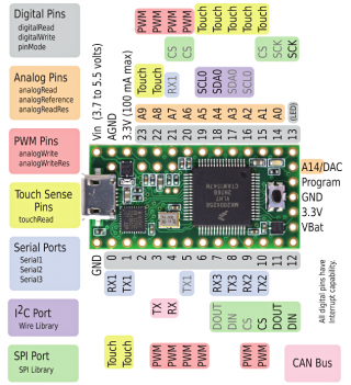
I'm using this ADC library on a Teensy 3.1, but having issues with getting information from A14. Has anyone else experienced this?
I have A14 grounded, so I'm expecting to see a value somewhere near 0, but I'm receiving a negative value and an error flag.

I ran across this issue using ADC.h in another sketch, but all other analog pins I am using are returning valid values except for A14.
When I use adc->analogRead(A14), I get an invalid result, which also happens when I run the example sketch. Using Arduino's standard analogRead(A14), however, I receive a valid, reasonable value.

To test this, I loaded up the example sketch bundled with the ADC library, changed the int values for readPin and readPin2 to A14 like so:

Code:
const int readPin = A14; // ADC0
const int readPin2 = A14; // ADC1

and then ran the sketch. I receive serial output like this:

Code:
Pin: 40, value ADC0: -56.4102564
Pin: 40, value ADC1: -3.5248340
ADC1 error flags: 0x10
Comparison error in ADC1

According to ADC_Module.h, the 0x10 error flag is defined as ADC_ERROR_CALIB. But, I'm not sure how the calibration is invalid, because it returns sane values for all other ADC pins I tested it on. This also happens in the example sketch.

To further test this, I put together the following code, which also produces a wonky value from A14:

Code:
/*
  ADC library testing. Comparing adc->analogRead(A14) to Arduino's analogRead(A14)
*/

#include <ADC.h>

ADC *adc = new ADC(); // adc object

void setup() {
    pinMode(A14, INPUT); //pin 23 single ended
    Serial.begin(9600);

    adc->setAveraging(1); // set number of averages
    adc->setResolution(12); // set bits of resolution
    adc->setConversionSpeed(ADC_HIGH_SPEED); // change the conversion speed
    adc->setSamplingSpeed(ADC_HIGH_SPEED); // change the sampling speed

    // always call the compare functions after changing the resolution!
    adc->enableCompare(1.0/3.3*adc->getMaxValue(ADC_1), 0, ADC_1); // measurement will be ready if value < 1.0V
    adc->enableCompareRange(1.0*adc->getMaxValue(ADC_1)/3.3, 2.0*adc->getMaxValue(ADC_1)/3.3, 0, 1, ADC_1); // ready if value lies out of [1.0,2.0] V
    Serial.println("End setup");
}

int value;
int value2;

void loop() {
  // using ADC library
  value = adc->analogRead(A14, ADC_0); // read a new value, will return ADC_ERROR_VALUE if the comparison is false.
  // using Arduino's built in function
  value2 = analogRead(A14);

  Serial.print("adc->analogRead() result: ");
  Serial.print(value);
  Serial.print(", voltage: ");
  Serial.println(value*3.3/adc->getMaxValue(ADC_0), DEC);

  Serial.print("Arduino analogRead() result: ");
  Serial.print(value2);
  Serial.print(", voltage: ");
  Serial.println(value2*3.3/adc->getMaxValue(ADC_0), DEC);
  
  delay(500);
}

And the results look something like this:

Code:
adc->analogRead() result: -70000, voltage: -56.4102564
Arduino analogRead() result: 9, voltage: 0.0072527
adc->analogRead() result: -70000, voltage: -56.4102564
Arduino analogRead() result: 9, voltage: 0.0072527
adc->analogRead() result: -70000, voltage: -56.4102564
Arduino analogRead() result: 10, voltage: 0.0080586

But, in this sketch, I'm testing both adc->analogRead() and the regular Arduino analogRead() function. Arduino's function returns sane values, whereas the adc->analogRead() returns -70000, probably due to the calibration error I mentioned earlier.

Is there a trick I'm missing to be able to use the ADC library on A14, or is this a bug?
 
A14 on the teensy 3.1 is the DAC for outputting a voltage. I assume it can't be used as an input.

card5a_rev7.png
 
I think it can be used as an ADC input, readable by ADC_0 only; -70000 happens to be what ADC_ERROR_VALUE is defined as (when I read the source code behind it all) and the note on the following line piques my attention about this;
Code:
  value = adc->analogRead(A14, ADC_0); // read a new value, will return ADC_ERROR_VALUE if the comparison is false.
 
I'll have a look at it. There's an array with all valid pins for each ADC module, most likely A14 isn't set properly!
 
robsoles,

I've run you sketch and I get good results, both the ADC and the core analogRead return the same (or very similar) values!
Using A14 in the example analogRead of the ADC library also gives the expected results. I don't know why you are seeing this, do you have the latest version of the library? I just updated it with a few improvements to the PDB stuff.

In the sketch you setup the comparison, but why do you set the normal comparison and then the range comparison on the ADC_1, when you are measuring on ADC_0? If instead of ADC_1 you write ADC_0 indeed analogRead would return -70000....
 
In the sketch you setup the comparison, but why do you set the normal comparison and then the range comparison on the ADC_1, when you are measuring on ADC_0? If instead of ADC_1 you write ADC_0 indeed analogRead would return -70000....

Regardless of whether I'm setting enableCompare() on ADC_0 or ADC_1, or comment the calls to enableCompare() and enableCompareRange() out entirely, I still receive the same results as outlined in my original post. I also tried commenting out all adc-> calls in setup(), and also receive the -70000 result from adc->analogRead(A14). Other Analog pins seem to work fine; it's simply the A14 pin that doesn't.

I just checked the Git repository where this library is hosted and I see that the ADC.h file is different than the version I have. The copyright at the top of my version of the file is 2014. The version I have was installed through the Teensyduino installer two weeks ago, so it didn't occur to me that it would be outdated and/or incompatible with Teensy 3.1.

Thanks for the help and the library!
 
Mmm, can you post the files ADC.h and ADC.cpp? Use the
Code:
 things. I just want to make sure this is indeed a problem due to an oudated library. If you installed it two months ago it seems unlikely, but it's worth the try.
 
Back
Top