newbie help - connecting led strip to Teensy 3.1

Status
Not open for further replies.

K G B

Member
Hi guys,

I have ws2811 LED strip of 28 leds. Only data, ground and live wire.
trying to play around with them but when I load a sketch provided in the forums for NeoPixel library "strandtest" sketch nothing happens.

Here is my setup:
-cut connection between USB and Vin due to LED strip requiring 5v input.
-temporary connected USB and Vin to upload a proper sketch (without connection it doesn't upload, right?)
-my 5v 30A power supply has been connected to LED strip
-LED strip ground wire connected to Teensy ground pin
-LED data wire (no clock wire) connected to Teensy pin 12

when sketch is uploaded nothing happens. Do I need to connect powersupply V to Teensy Vin pin as well?
I tried it with and without powersupply live wire connected to Vin but still nothing happens.

Sketch in questions is:
Code:
#include <Adafruit_NeoPixel.h>

// Parameter 1 = number of pixels in strip
// Parameter 2 = pin number (most are valid)
// Parameter 3 = pixel type flags, add together as needed:
//   NEO_RGB     Pixels are wired for RGB bitstream
//   NEO_GRB     Pixels are wired for GRB bitstream
//   NEO_KHZ400  400 KHz bitstream (e.g. FLORA pixels)
//   NEO_KHZ800  800 KHz bitstream (e.g. High Density LED strip)
Adafruit_NeoPixel strip = Adafruit_NeoPixel(28, 12, NEO_RGB + NEO_KHZ800);

void setup() {
  strip.begin();
  strip.show(); // Initialize all pixels to 'off'
}

void loop() {
  // Some example procedures showing how to display to the pixels:
  colorWipe(strip.Color(255, 0, 0), 50); // Red
  colorWipe(strip.Color(0, 255, 0), 50); // Green
  colorWipe(strip.Color(0, 0, 255), 50); // Blue
  rainbow(20);
  rainbowCycle(20);
}

// Fill the dots one after the other with a color
void colorWipe(uint32_t c, uint8_t wait) {
  for(uint16_t i=0; i<strip.numPixels(); i++) {
      strip.setPixelColor(i, c);
      strip.show();
      delay(wait);
  }
}

void rainbow(uint8_t wait) {
  uint16_t i, j;

  for(j=0; j<256; j++) {
    for(i=0; i<strip.numPixels(); i++) {
      strip.setPixelColor(i, Wheel((i+j) & 255));
    }
    strip.show();
    delay(wait);
  }
}

// Slightly different, this makes the rainbow equally distributed throughout
void rainbowCycle(uint8_t wait) {
  uint16_t i, j;

  for(j=0; j<256*5; j++) { // 5 cycles of all colors on wheel
    for(i=0; i< strip.numPixels(); i++) {
      strip.setPixelColor(i, Wheel(((i * 256 / strip.numPixels()) + j) & 255));
    }
    strip.show();
    delay(wait);
  }
}

// Input a value 0 to 255 to get a color value.
// The colours are a transition r - g - b - back to r.
uint32_t Wheel(byte WheelPos) {
  if(WheelPos < 85) {
   return strip.Color(WheelPos * 3, 255 - WheelPos * 3, 0);
  } else if(WheelPos < 170) {
   WheelPos -= 85;
   return strip.Color(255 - WheelPos * 3, 0, WheelPos * 3);
  } else {
   WheelPos -= 170;
   return strip.Color(0, WheelPos * 3, 255 - WheelPos * 3);
  }
}


If I load a Teensy example Blink sketch Teensy LED blinks so the upload part on my computer is working properly.


Any help is appreciated.

Regards,
Milos
 
Last edited:
No one?

Please just help me with the connection of teensy with external power and usb procedure so I know I didn't screw up something there.
 
There are various things it could be. Some obvious things are:

  1. If you have multiple power supplies, did you connect the grounds of all of the power supplies? Did you connect the ground to the Teensy and to the WS2812 strip?
  2. If you cut the trace between VIN and VUSB, you need to power the Teensy, and so you should connect the 5V to the VIN pin. This thread talks about cutting VIN/VUSB: http://forum.pjrc.com/threads/19228...ng-VIN-from-VUSB-Teensy-3-0?p=44024#post44024
  3. With the system setup, can you still program the system with something that doesn't use WS2812 LEDs, say with the blink demo program, and have it run?
  4. Adafruit has published an Uberguide for neopixels, have you read and followed the settings on the Best Practices guide? For small numbers of WS2812 LEDs, you might get away with ignoring some of the things, but if you are having problems, trying following all of the recommendations. https://learn.adafruit.com/adafruit-neopixel-uberguide
  5. Start small, can you illuminate a single neopixel first?
  6. If you soldered things, be sure to check all of your solder connections to make sure the electrical connection is solid, and that you are not creating a solder bridge to make a short by accident. Hopefully you are better at soldering than I am, I have ruined at least one ring applying too much heat, and melting the area around what I was trying to connect.
  7. While it may work (so far my small number of rings and sticks work without shifting), you probably should use an appropriate level shifter on the signal to go from Teensy's 3.3v to the Neopixel 5v. This article talks about various shifters, and comes to the conclusion that the 74HCT245 is the best, and the TXS-0102 will work for small numbers of LEDs: http://happyinmotion.com/?p=1247.
  8. The octows2811 shield that PJRC.COM sells incorporates the 74HCT245, resistors, etc.: http://www.pjrc.com/store/octo28_adaptor.html. It also contains guides on how to wire up large displays.
  9. There are at least 3 libraries for doing WS2812 lights. I use the Adafruit neopixel library. The earlier library needed to be patched for the Teensy, but I believe the current version runs ok on Teensy 3.0/3.1's unchanged. There is Paul's octows2811 library to write streams of 8 parallel leds, and the fastled (fastled_spi) library is another library. You might want to start with the Adafruit library to get the basics ironed out.
  10. Have you made sure that you are getting 5v to the rings and Teensy's VIN pin?
 
Awesome reply MichaekMeissner, thank you.

I only have one external power supply. I'll go through your sugestions in detail when I'm back home from work but from a quick glance I have problems powering Teensy from external supply.
Connecting 5v to vin doesn't power up teensy at all. only when I connect the vin and usb back up does it work.
So I must be doing something wrong there. I purchased new 3.1 Teensy thinking I fried the old one. At least I know now that is how it should be and something is wrong on my end.

Thank you
Will report back soon.
 
It sounds like you are only connecting the power wire to VIN and not the ground wire. To make a complete circuit, you need both connections. Be sure to connect the + to VIN and - to Ground. If you have a multimeter, check your current, just in case something got mis-labeled, and the red wire is ground and black wire is power (it would read negative volts if the wires are backwards). I recall reading over in the Adafruit group, that some number of the 2.1mm connector wires had the polarity swapped, and it wasn't noticed since often the cables were typically used in A/C circuits.

Note, VIN is the first pin on the right hand side (if the USB is facing up). Ground is the first pin on the left hand side (or the middle pin in the back). Do not hook it to the 3rd pin on the right (which is 3.3v after regulation). So VIN is the voltage before the power is regulated down to 3.3v (i.e. 5v if VIN and VUSB are connected).
 
Last edited:
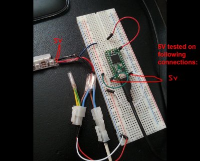
2014-05-24 13.13.33.jpg
Ok So I tested the power supply cables and other connections marked in image and all show steady 5.01v.
Yet the Teensy is not powered at all.

Blink test works when I connect Vusb and Vin with USB connected - and I can also upload my sketches.

When Vusb is disconnected from Vin and 5v power supply is connected (with ground wire and live) Teensy is powered off - no blinking and no sketches can be uploaded.
If you guys say that Teensy should be powered when connecting 5v live to Vin and ground to Teens ground then I am unsure why mine doesn't work. This is all done with new 3.1 which I didn't have a chance to destroy in any way. Yet it works fine with Vusb to Vin connection.
 
Last edited:
Status
Not open for further replies.
Back
Top