Teensy 3.1 Power supply clarity.

Status
Not open for further replies.

balornt

Member
I want to run the Teesny 3.1 on AA batteries. I would like to minimize the number of batteries required. I know the Teensy 3.1 pin has a 5v modulator so it expects 3.7v - 5.5v on Vin to operate at max speed. There is also the two 3.3v pins which I assume are generally used for output voltage, but could I use one of them to power the teensy with 3.0v (two AA batteries)? with 3.3v (with step-up board)? Assuming that I wish to run the Teensy 3.1 on AA batteries and that I want to minimize the number of batteries required. How would you recommend I do this.

(P.S. Your "How-To Tips" seem to need an update)

Edit: So a recent post has revealed that you can supply regulated 3.3v to either 3.3v pin of the Teensy 3.1. I am still looking to see if 3.0v is possible, but my best guess is that if it is that you will lose processor speed.
 
Last edited:
There are boost regulators available at Pololu that will take the output from just about any battery pack and bring the voltage up to 3.3V. Some regulators even allow buck/boost operation. A downside of a switching regulator like this (besides cost) is the noise it produces. If you need a very stable analog voltage reference, you may need to work on getting the noise out of the AREF/etc. power supply. However, you end up with a power supply that is stable pretty much regardless of the state of the battery, which should help trouble-shooting later on by eliminating one potential reason that a MCU may be acting strangely.
 
I have a portable gadget that I power from a 3.7V Lithium Polymer battery. The battery is wired to Vin and GND at the connector end of a Teensy 3.0, so power is going through the Teensy's voltage regulator. Since my application is just a toy, I'm not too worried about what happens when the battery drops below the datasheet value. The application runs for hours without any steps taken to reduce power other than running at the minimum supported clock frequency. The battery is rechargeable. I do notice that the current supplied by the outputs diminishes as the battery runs down. I don't recall the exact voltage when the Teensy can't run any more but I think it was around 2.8V. I use an Adafruit Micro Lipo to charge the battery.

This is a very simple solution and it fits in an Altoids Smalls tin. Details and pictures in my sig.
 
Makes sense that would work since the Teensy MCU is presumably targeted at the mobile market with its ubiquitous LiPO battery voltage range.

That said, I would ensure that your battery pack has a auto-cutoff disconnect feature to ensure that the battery is not run down too far. Otherwise, you will damage it, even on a low power draw. Some modules feature this switch, others do not.
 
After considering my project, I don't want to take the risk of running lower voltages. For this project, spending a few dollars on a voltage regulator is not a big deal but battery efficiency is important. Which generally provides the most usage time per battery:
1. Using 2 AA batteries (3.0v) with a step-up regulator
2. Using 3 AA batteries (4.5v) plugged directly into Vin
 
Good point! The Sparkfun battery description says: "Battery includes built-in protection against over voltage, over current, and minimum voltage." :)

Initially, I considered programming the Teensy to manage and charge the lipo battery. After watching a few videos of batteries catching fire, I put that project on the back burner, so to speak. <ducks>

What happens when a battery can no longer supply enough current for a microprocessor board like a Teensy 3? Does the microprocessor stop drawing current or does it drain the battery while continuously attempting to restart?
 
A downside of a switching regulator like this (besides cost) is the noise it produces. If you need a very stable analog voltage reference, you may need to work on getting the noise out of the AREF/etc. power supply. However, you end up with a power supply that is stable pretty much regardless of the state of the battery, which should help trouble-shooting later on by eliminating one potential reason that a MCU may be acting strangely.


How much noise are we talking? One of the modules I will be using requires 3.3v +/- 0.3v.
 
Last edited:
After considering my project, I don't want to take the risk of running lower voltages. For this project, spending a few dollars on a voltage regulator is not a big deal but battery efficiency is important. Which generally provides the most usage time per battery:
1. Using 2 AA batteries (3.0v) with a step-up regulator
2. Using 3 AA batteries (4.5v) plugged directly into Vin

Not having a regulator would be the most efficient so i would go with 2, plus then you don't have switching reg noise issue.
 
Not having a regulator would be the most efficient so i would go with 2, plus then you don't have switching reg noise issue.

True, but you end up having a regulator either way. Number 2 uses the built-in regulator connected to the Vin pin, but number 1 uses an external regulator that is connected to a 3.3v pin.

The noise may not matter to me, it depends on how much there is. Can anyone answer that?
 
Last edited:
The noise may not matter to me, it depends on how much there is. Can anyone answer that?

Check the specifications of the power supply vs. the sensitivity of your measurements. One reason that many folk advocate a linear regulator downstream from a switchmode regulator is just that - noise removal. So I'd frame it in the context of the ENOB you're trying to achieve and comparing that to the noise the power supply could be adding to your AREF pin, even if you're using a shunt zener to bring it to a 'constant' voltage. At 13 bits (the effective ADC limit of the Teensy) and AREF=3.3V, you're looking at resolving 0.000402832 Volts per bit. Less, if you use a reference voltage that is lower than 3.3V.

So it's easy to pick up noise with the ADC. Designing your board to keep noise away from analog sections (see Henry Ott's work, among others) is hard and I'm impressed that Paul was able to pick up analog pins from all around the K20 chip and route them to a single side of the Teensy PCB while maintaining 13 bits of resolution (that is a great achievement!). So if you're planning on using a switching regulator and need to make higher-resolution and/or fast ADC measurements, you may want to take a close look at the AREF voltage stability with a quality oscilloscope. If that line isn't absolutely flat (up to several hundred kHz to ensure you get harmonics), you'll have to deal with the noise in one shape or the other (decimation/oversampling, better power supply decoupling, etc.)

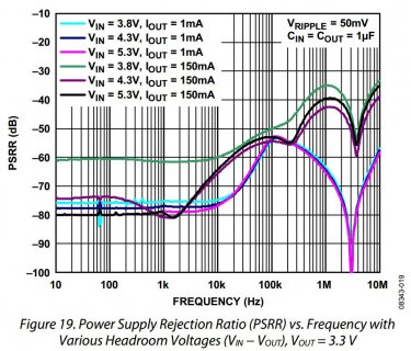
FWIW, a recent PCB I put together features a separate ADP150 voltage regulator for the digital as well as the analog power supply to the quasi-24-bit ADC I'm trying to optimize the performance of. One feature I really liked about this voltage regulator is it's very high Power Supply Rejection Ratio (PSSR). For my application, below 10kHz, it's about -80dB, rising to -50dB at 100kHz, before dropping again. Not all voltage regulators publish a PSSR and even fewer publish a graph that illustrates the performance of the regulator based on power draw, voltages (in and out), capacitors used, as well as frequency. Given how easy it is to measure these regulators for PSSR, my guess is that most voltage regulator OEMs are not publishing the performance in a like manner for a reason. Maybe it's because they don't want 'reference regulator' sales cannibalized or perhaps the less expensive regulators simply don't perform well re: PSSR.

PSSR.jpg
PSSR Chart from ADP150 datasheet, courtesy Analog Devices

While the ADP150 doesn't provide a lot of power (only 150mA max, if you have oodles of board space dedicated to cooling purposes), it's more than enough to keep the MCP3911 happy, and certainly a step above the MCP voltage regulators that MCP advocates in its reference designs (presumably due to cost and brand loyalty reasons). For example, the MCP1700 and MCP1703 have a PSSR of -44dB at 100Hz, whereas the ADP150 is around -80dB there. Why this effort, well, the MCP3911 can allegedly resolve 1.83105E-05 volts per bit - even if the MCP3911 internal reference power supply is presumably very stable (only 7PPM/*C drift, among other features) - I figure, throw some additional $$$ at the BOP around the chip to ensure it can do it's best. The boards are now on a plane... wish me luck!
 
Last edited:
While on the topic of LDO. I have a project where I need to power a load cell, the teensy and an SD card. At the moment the only 5v regulator I have on hand is the LM2931. I am just wondering if there is a better 5V LDO I could use. My results have been ok, after doing a moving average I can get ok resolution, but still noise in the signal. I am very new to electronics and just use what I can get my hands on. However I have to build a few of these systems and if I am going to order stuff, I want to know what I should get. The LM2931 only provides 100mA, but I have had no issues with writing to the SD card, but wondering if I should get an LDO that can provide a bit more current. Thanks again for all the insight Constantin, this forum is a great place to learn.
 
It would be helpful to understand this system better, i.e. a schematic would help.

For example, what powers the load cell vs. the Teensy vs. the SD card? For sensitive measurements, at the very least I'd consider a separate power supply for the bias currents in the load cell. If there is an external ADC involved, power it off the same power supply as the load cell if that's OK with the OEM.

The ADP150 only costs $0.20 more than the LM2931 at Digikey, for example. The ADP150 has a output noise ripple of less than 1μVrms/V whereas the LM2931 has 100μVrms/V specified. So it seems that there are better solutions out there to power the load cell and/or the ADC that is reading it. Especially when you consider that at 3.3V and 16bits of ADC resolution, your resolution is about 50μV per LSB. At lower supply voltages or higher resolutions, noise becomes even more problematic. For example, the MCP3911 samples at 24 bits with a reference voltage of 1.2V which leads to an alleged 0.01μV per LSB resolution.

Thankfully, the folk at MCP have also published enough data in the datasheet to prove that the ENOB out of a reference system is unlikely to be better than 16bits, so they made it possible to just read 16-bit values out of the analog front end and ignore the additional 8 bits that are unlikely to contain more useful information than the decimated/oversampled results that the MCP3911 created from the thousands of measurements per result.

Very careful layout is also necessary, the higher you try to push resolutions. Pay extra attention to signal and return paths, PCB segmentation, decoupling, and so on. I have tried my best to digest everything Henry Ott suggested to make my power sampling board as 'quiet' as possible in the analog section. For example, I transitioned the board from the inductor/ferrite-approach used by Paul and others to using a single ground plane that is trenched (analog vs. digital) and which also comes together under the MCP3911 chip. No signal or power lines jump the trench, the two power lines run under the chip... it will be interesting to see whether this board will be more sensitive / accurate than the preceding ones.
 
Last edited:
Sorry about that, should of given a bit more info. Right now the LM2931 is powering everthing. The load cell is just a cheap micro one that has 1k ohm resistance. I was thinking I should have two separate voltage regulators, however trying to fit this into a small space, but I guess getting a surface mount solution might be better. I will look into the ADP150, however right now I use random walwarts, so they range from 9V-16V, and I see the ADP150 takes 5.5V, so that might not help. Also, I am just using the teesny 3.1 adc. Thanks again for the info.
 
I see. So you are powering the Teensy via a power jack, that feeds the LM2931, which feeds the Teensy, which produces its own 3.3V? Since the Teensy won't measure 0-5V on it's inputs, I presume you're powering the load cell off the 3.3V power supply in the teensy? What kind of a voltage swing are you getting out of the load cell? Have you measured the stability of the Teensy power supply under load (i.e. esp. as it writes to the SD card)?

I would be surprised if SD card writes wouldn't cause the Teensy power supply to have a fun time producing the current without any kind of sagging.

Also, the ADC inside the Teensy may or may not be good enough to handle the variation in load cell output voltage... At the very least I'd consider using an external Zener diode as a shunt reference on AREF as described by Paul to make the AREF voltage more stable than the Teensy output, especially when it's dealing with SD-card related power spikes. Then use AREF as an input into your load cell. The resistor for the shunt reference is already there, you just have to determine what you'd like to use as a reference voltage (2.5V? 1.8V? etc)

Or, furnish an external regulator for the AREF pin, which works as long as you disconnect the 470 Ohm resistor connecting it to the 3.3V power supply coming out of the K20 chip. The ADP150 can be hand-soldered with a fine tip or you can buy a breakout board for SOT23-6 chips and hot skillet it with a small dollop of solder paste via a syringe on each pad.
 
Last edited:
Well the load cell is on 1mV/V, so a tiny swing, but the differential ADC with PGA does ok, and the sense voltage is around 2.4V, so I could use a 2.5 reference voltage. I am trying to keep the costs as lost as possible since this is for an unfunded PhD student, so just trying to get best possible signal with what I have. However now that you mention drift, I think that is happening when collecting over a few minutes, I thought it was just due to the crappy load cell. I think I might just add a 3.3 regulator to deal with the SD card, and the 5V regulator will power the teensy and load cell. I am not really sure what you mean about the shunt reference. I have tried to search it and even looked in the Art of Electronics, however I seem to be missing something, I guess it is one of those basic electronic things everyone knows about.
 
I have tried to search it and even looked in the Art of Electronics, however I seem to be missing something, I guess it is one of those basic electronic things everyone knows about.

Apologies, I didn't put the words in the right order. Zener diodes have been used happily as voltage references and all you need is a breakdown voltage of choice and a current- limiting resistor. The resistor is already included as part of the teensy pcb. Here are some general use 2.5v Zener diodes in through hole as well as smd form: 2.5v diodes at digikey

These are cheap but relatively imprecise. However, as long as the adc and the load cell use the same reference voltage, you should be ok. Apologies again for jumbling the words, it was an oversight and I'll fix it above for posterity.
 
Last edited:
Ok, thanks, I can now learn all about Zener diodes. What confuses me is, the load cell needs 5v, but the sense voltages are just under half the input voltage, so really, the adc and load cell are not using the same reference voltage, or am I confusing the two. Since I am reading differential, this should help with the noise. I have some diodes, but they are the usual 400X, will assume I can't use those. I just powered the SD card using its own 3.3 regulator and it helped a lot, reduced the noise by half, plus don't have the slow drift in signal. Since I don't need super accurate for this project, it might work as is. However future projects are going to need this accuracy. Thanks again for all your wisdom.
Also, would this guy be a good choice for both my 5V and 3.3 regulator http://www.digikey.ca/product-detail/en/L4931CZ50-AP/497-5838-3-ND/1038130 Seems to have output noise of 50uV, which seems a lot lower than 500uV, which my current 5V regulator has. Trying to make sense of the spec sheet, but in reality I dont have much of a clue.
 
Last edited:
What confuses me is, the load cell needs 5v, but the sense voltages are just under half the input voltage, so really

It would be helpful if you could post the spec sheet for the load cell. Since load cells are basically varistors, I would be surprised if the voltage you're referring to is not the maximum allowable voltage that doesn't cause excessive self-heating. If you look at this link from TI, they are quite explicit re: the need of your ADC reference voltage and the load cell input voltage to be the same. By using the same reference voltage, any disturbance on the voltage supply side is referenced and hopefully canceled out by affecting the reference voltage input and the ADC input equally (on a ratiometric basis).

So, if you are using a Teensy 3.1, I would address the low differential voltage difference of the load cell by enabling the Programmable Gain Amplifier (PGA). Pedro's library allows a gain of up to 64x, IIRC. Not sure how the PGA works though, so read up on it too. At the very least, with a gain of 2x, the PGA will double the output voltage of your load cell, bringing its output range back into the same range as the Reference voltage input (AREF). So I'd consider using a 2.5V zener diode (GND to AREF) to produce a stable AREF power supply, then run the AREF voltage into the top of the load cell, then use the PGA to bring the input signals up. Adds perhaps a bit of noise (PGA) but likely eliminates a lot of noise and drift.

Having a separate reference voltage for the bridge and the ADC input is IMO a recipe for disaster. Don't do it. For example, if the thermal drift characteristics of your voltage regulators vary (and they more than likely will), then the voltages can drift at varying rates as a function of ambient thermal conditions. You'll pull your hair out in frustration, as calibrating that will result in a rig that will only will work at one temperature. OK for some applications, but really bad design practice, IMO. Of course you could throw lots of bucks at the problem by buying precision references that have very low thermal drift characteristics, but you'd essentially be throwing money at a problem that shouldn't exist in the first place.

If you end up needing something more accurate and capable of handling temperature-induced drift better than the cheap zener diodes I referenced above, consider a shunt-style reference as an alternative for out-of-box Teensy compatibility. Digikey is carrying a number of them. For through-hole shunt references with accuracy of 1% and up, see this list. Even a 0.1% reference can be had for less than $2 in single quantities. I doubt you need something that accurate as long as AREF=Vin for the load cell, but it's available.

Also, if you want to use a series reference instead of a shunt-style reference, you need to remove the 470 Ohm resistor from the Teensy board that ties AREF to 3.3V.
 
Last edited:
I am not surprised that the voltage you are measuring is 0.5 X 5v.
If you look at the drawing 5v is put across A-C. The voltage at D is divided down by R1 and R2. So voltage at D is R2 / ( R1+R2). Now R1 and R2 will be the same so 5v/2.
The Sensor voltage you will be reading will be between D and B. The voltage at B will be Rx/(R3+Rx).
That is the voltage (D-B, difference) that you wish to measure.Wheatstone[1].png
 
Last edited:
Thanks again. I have been using Pedros library and using PGA of 64x, since we are talking about such small values. I am starting to understand most of what you are saying, but I am worried that if I feed the load cell with only 2.5V, then I lose the range since the output voltage is half of the input.That is why I thought if I feed it with 5V, the reference voltage of 2.5V would be fine. If this is the case, then i'd just get a better 3.3V reference voltage, or try to feed the loadcell with 3.3V. In my code I am already doing a running average that is spit out at 200 samples/second, so my error right now is pretty low when using a separate 3.3V supply for the SD card, at least good enough for this project. I will make sure to read your link about load cells and will start to read up on reference voltages. I am meeting with the other lab that needs this, and then I will have an idea of how accurate they need their measurements to be. Thanks again so much for the help.
 
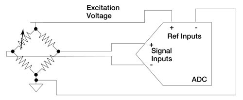
This drawing shoes a bridges sensor attached to an ADC. In the worse case for the sensor it can go open circuit or short circuit causing a swing on the negative input to the ADC of +/- Excitation voltage / 2. I am not too clued up on using ADCs especially in a ratiometric input like this. Has anyone got a 101 of using ADCs. I am sure that that will help all round.
Ratiometric_Measurement_of_Load_Cell_with_an_ADC.jpg
 
I'd try using one reference power supply just for the AREF and Vin of the bridge to see if the loss in noise outweighs the loss in output. My guess would be that a common power supply using a shunt reference will help a lot more than the loss of output signal will hurt your results. It's easy enough to try out.

Lastly,IIRC, AREF can be as low as 1V, or thereabouts. You could use an external zener diode to create a 2.5V reference then connect it to the load cell + and -, as well as AGND. Remove the 470 Ohm Resistor on the teensy board and use two resistors as a voltage divider and hence make AREF = 1/2 of VReference (2x 1kOhm, for example). Such resistors (in the through-hole format you seem to prefer) cost as little as $0.13 each for a resistor that offers less than 100PPM/*C thermal drift. For all I know, this adds more issues than it solves, however.

So see if a single common reference doesn't solve the problem.
 
Last edited:
I will try to get a zener diode and try that out. I am also thinking I should at least try a 3.3V reference and see how that works, since I am splitting the output voltage in half from the load cell. Just to make sure, if I get the diode, I just attache it to ground and AREF and then also get the reference voltage from that for the load cell. I assume when you call analogreference(external), it then expects an input on that pin instead of an output. Also I was trying to measure the AREF voltage, and when I set it to internal, I assumed I would see 1.2V on the AREF pin, however I only saw 3.3V. Does this make sense or does the AREF pin always produce 3.3V and that only the internal reference is routed to the ADC.
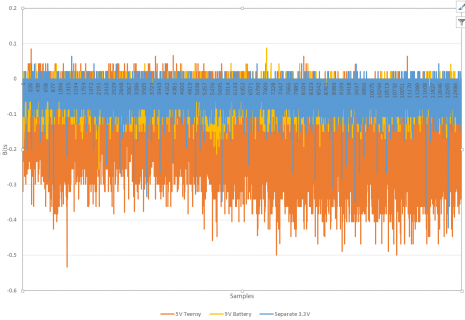
Here is an image of my testing. As you can see, I am only getting around 0.2bit noise when using a separate 3.3V supply to the SD card. I am actually doing an analog read average of 32 every 100us, in which I then average these 25samples every 5ms, so, as you can see, I am doing a massive amount of software averaging. But you can see when using the 5V from the teensy and supplying 3.3V to the SD card from the teensy is not good, plus you can see how much drift starts in the signal.
LoadCell_Testing.png
 
Last edited:
I will try to get a zener diode and try that out. I am also thinking I should at least try a 3.3V reference and see how that works, since I am splitting the output voltage in half from the load cell. Just to make sure, if I get the diode, I just attache it to ground and AREF and then also get the reference voltage from that for the load cell. I assume when you call analogreference(external), it then expects an input on that pin instead of an output. Also I was trying to measure the AREF voltage, and when I set it to internal, I assumed I would see 1.2V on the AREF pin, however I only saw 3.3V. Does this make sense or does the AREF pin always produce 3.3V and that only the internal reference is routed to the ADC.

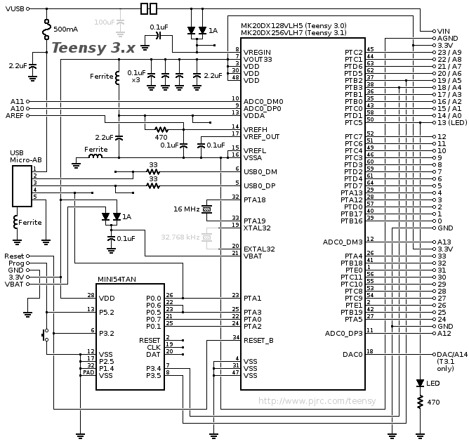
AREF is an input into the ADC of the K20 chip. It is attached to the 3.3V rail via a ferrite and a 470 Ohm resistor, see the left side of the Teensy 3.1 schematic:
schematic3.gif

A ferrite connects Vout33 (pin 7) to the ADC power supply (VDDA). A 470 Ohm resistor then connects VDDA to the AREF input. A shunt between AGND and AREF then allows you to vary the AREF voltage from about 3V down to about 1V, if memory serves. AGND in turn is attached to GND via a further ferrite. A 2.2uF capacitor provides some decoupling.

This is why the external AREF pin features 3.3V by default - it is connected directly to the output of the K20 voltage regulator. When you set the ADC to use an internal reference (1.2V?) it ignores the external ADC voltage altogether.
 
Thanks for that, now it is making sense, just needed to follow the lines. So, the zener diode shunts away voltage from the 3.3 source to produce 2.5V. So what happens is I try to use a 3.3 shunt? Will it just help create a more stable voltage since if the load cell excitation voltage varies, the ADC is seeing the same change.
 
Status
Not open for further replies.
Back
Top