ADC noise with OctoWS2811?

Status
Not open for further replies.

farman

Member
I'm trying to build some sound sensitive shirt which uses OctoWS2811 using the Adafruit mic breakout board (https://www.adafruit.com/products/1063) on a Teensy 3.1.

With no sound playing, running the following code, I find I get much larger noise if I'm calling OctoWS2811's show() method in the same loop(). (Something like ~400 vs ~50). I've tested with an external pre-amp circuit on the same pin and don't see the same noise difference and the main thing I can think of is that the external pre-amp circuit has a cap on it's power supply. Both my circuit and the breakout board are being powered from the 3.3V output of a Teensy 3.1.

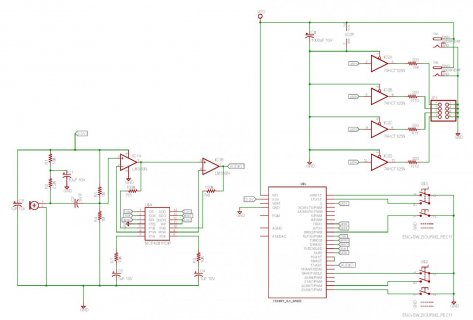
The attached schematic is close to what I'm testing with. Differences include:
- R6 is 10K
- VIN isn't attached to VDD, Teensy is powered via USB.
- VDD is 5V wall wart
- At the end of R9 is the data line for a NeoPixel 8x8 grid, currently unplugged/unpowered.
- In the problem configuration, the out of the breakboard is attached directly to A3 (I've also tested it with A4).
- Have a 74HCT244 attached instead of the 74HCT125.

I was thinking that the power supply is being drained too much with the DMA and a capacitor across the 3.3v would help. I don't feel confident about this idea because the other circuit is still attached to the 3.3v with it's capacitor.

Using 10 bits analogReadReference() and analogReference(DEFAULT) (do I need to attach AREF back to 3.3v?). I've tried both with and without analogReadAveraging(16) without any major difference.

Thanks in advance...
Code:
    int min = analogRead(AUDIO_INPUT_PIN);
    int max = min;
    for (int i = 0; i < 10000; ++i) {
        int value = analogRead(AUDIO_INPUT_PIN);
        min = min(min, value);
        max = max(max, value);
    }
    Serial.print("m=");
    Serial.print(min);
    Serial.print(" M=");
    Serial.print(max);
    Serial.print(" D=");
    Serial.println(max - min);

bloop.jpg
 
I just realized I didn't actually add the capacitor on the other circuit with the LM358 which isn't experiencing the same noise.

I'm trying to build some sound sensitive shirt which uses OctoWS2811 using the Adafruit mic breakout board (https://www.adafruit.com/products/1063) on a Teensy 3.1.

With no sound playing, running the following code, I find I get much larger noise if I'm calling OctoWS2811's show() method in the same loop(). (Something like ~400 vs ~50). I've tested with an external pre-amp circuit on the same pin and don't see the same noise difference and the main thing I can think of is that the external pre-amp circuit has a cap on it's power supply. Both my circuit and the breakout board are being powered from the 3.3V output of a Teensy 3.1.

The attached schematic is close to what I'm testing with. Differences include:
- R6 is 10K
- VIN isn't attached to VDD, Teensy is powered via USB.
- VDD is 5V wall wart
- At the end of R9 is the data line for a NeoPixel 8x8 grid, currently unplugged/unpowered.
- In the problem configuration, the out of the breakboard is attached directly to A3 (I've also tested it with A4).
- Have a 74HCT244 attached instead of the 74HCT125.

I was thinking that the power supply is being drained too much with the DMA and a capacitor across the 3.3v would help. I don't feel confident about this idea because the other circuit is still attached to the 3.3v with it's capacitor.

Using 10 bits analogReadReference() and analogReference(DEFAULT) (do I need to attach AREF back to 3.3v?). I've tried both with and without analogReadAveraging(16) without any major difference.

Thanks in advance...

Code:
    int min = analogRead(AUDIO_INPUT_PIN);
    int max = min;
    for (int i = 0; i < 10000; ++i) {
        int value = analogRead(AUDIO_INPUT_PIN);
        min = min(min, value);
        max = max(max, value);
    }
    Serial.print("m=");
    Serial.print(min);
    Serial.print(" M=");
    Serial.print(max);
    Serial.print(" D=");
    Serial.println(max - min);

View attachment 2028
 
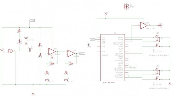
So I built a board along the lines of this schematic where the Teensy fits into a bigger board with a mic and two-stage amp along with a 74HCT125N output stage to control some neopixels. I switched over to using Paul's Audio library and am using the updated OctoWS2811 that's supposed to work with it.

Using the AudioPeak filter and graphing that at 30Hz I'm finding that without calling show(), I'll see peaks around 18000 (just the background noise in my apartment). As soon as I start calling show() (that's the only difference between the two runs) at 30Hz the peaks are all around 60000-64000. I've only got a single strand of 64 neopixels attached to a single output, and they're all set to black.

Any ideas about what might be going on?

lush-sch.jpg
 
Last edited:
Bump.

Anyone got any ideas about this? I still haven't found a real solution. I found that if I ignore peak readings that occur while OctoWS2811 is busy (and one or two after that), then I can get reasonable results out of the peak detector, but that doesn't really help when I want to do actual analysis of the audio data without missing any during frame refresh.
 
Unfortunately I don't have a solution for you but I can say you're not alone.

I tried something similar last weekend (but with a spectrum analyzer instead of peak readings) and had this problem. I've tried microphone+opamps from Sparkfun and Adafruit and a design I found on the web, using both the Audio library's AudioAnalyzeFFT256 and Adafruit's fun-with-fourier-transforms code, and all combinations show a lot of noise at the low end when OctoWS2811 is running.

I've put the audio portion of my project on the back burner while I play with FadeCandy temporal dithering and trying to optimize drawing speed, but I'll report back here when I get back to it.
 
Finding a relationship between the noise and the data rate to the WS2811's might might be a pointer in the right direction... Some hints might well be to use bulk bypassing of the strip power (100 - 220uF @ every 6 to 12 inches on the strip Vcc) and perhaps most important would be to re-wire everything to utilize a star topology for power and ground. This is where everything has it's own power and ground leads terminating at their individual Vcc sources, assuming that you are using both 5 and 3.3V if not split then all to the same 2 points. The reasoning is relatively simple.. If you take a piece of wire... Say a ground and put the high current load at one end and ground at the other.. then connect the audio circuitry in the middle there will be a noise current flowing in the ground.. This lifts the audio circuitry above ground by the noise current flowing in the ground lead. Capacitor decoupling helps sometimes enough to sufficiently alleviate the condition and some times only the Star Topology will get rid of the high current supply noise.
A third consideration is the '244/5 those are generally quite fast in switching, the outputs are "Totem Pole" and there can be a sharp spike as the N and P devices switch from low to high and back. both the lights and the gate package are great potential sources of noise.
One more approach too.. Might be a sharp filter @ the primary noise frequency. I've, in the past used Twin Tee type filters because they are relatively easy to construct and the circuit Q is variable to a certain amount by making the R/2 leg to ground a pot... If there is interest I'll try to remember the formula.. I've used them with good success from 500 Hz to 3 KHz..

Doc
 
Last edited:
Finding a relationship between the noise and the data rate to the WS2811's might might be a pointer in the right direction... Some hints might well be to use bulk bypassing of the strip power (100 - 220uF @ every 6 to 12 inches on the strip Vcc) and perhaps most important would be to re-wire everything to utilize a star topology for power and ground. This is where everything has it's own power and ground leads terminating at their individual Vcc sources, assuming that you are using both 5 and 3.3V if not split then all to the same 2 points. The reasoning is relatively simple.. If you take a piece of wire... Say a ground and put the high current load at one end and ground at the other.. then connect the audio circuitry in the middle there will be a noise current flowing in the ground.. This lifts the audio circuitry above ground by the noise current flowing in the ground lead. Capacitor decoupling helps sometimes enough to sufficiently alleviate the condition and some times only the Star Topology will get rid of the high current supply noise.
A third consideration is the '244/5 those are generally quite fast in switching, the outputs are "Totem Pole" and there can be a sharp spike as the N and P devices switch from low to high and back. both the lights and the gate package are great potential sources of noise.
One more approach too.. Might be a sharp filter @ the primary noise frequency. I've, in the past used Twin Tee type filters because they are relatively easy to construct and the circuit Q is variable to a certain amount by making the R/2 leg to ground a pot... If there is interest I'll try to remember the formula.. I've used them with good success from 500 Hz to 3 KHz..

Doc

I see the problem even without any LEDs actually being attached. As soon as show() starts getting called, my ADC readings go crazy.

I can't easily remove the level converter right now, but I will see if I can try that.

I'm using one of those 3"x3" boards with all 64 LEDs attached as a single strand so I don't really have a way of moving to a star topology. I'm just using a single output attached to LEDs.
 
In cases where there were components like the WS2811 I used a piece of scrap PCB and cut a small notch down the middle, Vcc was one 'Rail' and gnd the other. Each 'rail' ws 1/2 in (12 mm) wide... I do feel you might try something similar, Each device was connected to the power rails and they went to the power supply directly as did the audio processing and so did the controller.. Just a thought..
Do you use shielded audio cable to the audio board input.. If not, it too might just be the single answer. RG174 is easy to use as is RG316... They were what I had i the lab where I worked and suitable to purpose.. Of course regular Audio grade shielded cable willl work as well and short grounds are required. A cm is getting long...
All of what I mentioned are basic design practices for both modular and single board devices. Remember to make the PCB power rails at least 1 - 2 mm wide and use a ground plane to reduce noise currents from the high speed stuff.. My engineering instructor a long time ago told me that engineering is a series of successive aproximations.. Some have few steps and some have many..

Doc

Addendum: I've used these techniques from DC to UHF frequencies.. for nearly 40 years.
None, one or perhaps all might be the answer.. Or not. but watch which makes the most noticeable effect and try another.. perhaps the capacitors can be used as probes from Vcc to ground.. When the amplitude of the noise changes you're getting closer to a solution
However they are all valid to purpose and useful at one time or another For me today, retired and sitting home and playing.. Like I could never do before... Doc
 
Last edited:
There's no audio board -- it's just the electret mic on the board with that amplification circuit. What do you mean by using a capacitor as a probe?

I attached a scope and saw that as soon as I'm calling show() I see noise on the VIN, 3.3V off the Teensy board, and at the pin I've got the amplified output going into the Teensy at. The bursts of noise occur at the same 30Hz frequency I'm calling show() and they last about 2ms each time which is what I'm guessing is the time to actually write the pixel data out. I tried adding .1uF caps across the supply pins of each of the 3 ICs, and also directly tied AGND and GND. I saw similar results with the board powered by USB and Li-po battery, with and without any LEDs attached.

On the 3.3V I saw the following when powered by my Li-po battery:
show() being called, pixels attached: Vpp 124-132 Vavg 3.27v
show() not being called, pixels attached: Vpp 44-60 Vavg 3.27v

show() being called, no pixels attached: Vpp 84-92 Vavg 3.27v
show() not being called, no pixels attached: Vpp 40-48 Vavg 3.27v

I'm wondering if a bigger cap for C5 to smooth out the 3.3V side which might help clean up the input to the ADC? Or maybe change the cap C6 might help to smooth out the VIN spikes which might improve everything?

Has anyone successfully had ADC while the OctoWS2811 library was being used?

I need to spin another rev of my board in the next day or so so it'll be done in time for my festival, but I was really hoping to sort this issue out before doing so. I am planning to use much bigger traces for the power and a ground plane next time.

Thanks for all your help so far!
 
You are Most welcome,I'm very happy my thoughts were of use to you
My reference to a capacitor was to use it as a probe to find where the noise is highest by noting any reduction in the noise..
By modifying things slightly you can often locate the real issues quickly.
I think that I recommended a 100 nF cap on each IC, as close as possible and a 10 uF cap every third device. In addition a few 220 to 1000 uiF caps are cheap and might well do magic. My primary background is mixed signal and RF engineering..
Ground planes are a necessity, as are massive multiple bypassing, The parts are cheap and so are the pads and holes required.. You don't necessarily have to populate those pads and holes... But it is expensive to make room for them.
Another valid technique is ferrite beads used as Pi section filters, Type 77 material is good for sub MHz filtering.. sometimes 2 or 3 beads are really useful. As well as a capacitor cocktail.. .001, .01 and 10 uF paralleled caps are frequently required.
From an engineering stand point, anything that reduces noise.. Like that cap as a probe for noise, shielding and proper power distribution.. ie a star topology for power and a solid backplane/ground plane reduces the high impedance points that are susceptible (same or close impedance as the noise source) to both power and return induced noise. This was the hardest thing to get across to my techie trainee's. There is a world of difference between static power distribution and dynamic noise distribution.. All wires and PCB traces are or can be readily modeled as inductors which are or can be looked at as resistors that vary with frequency. Capacitors act to decouple the noise (short it to ground) in conjunction with the inherent inductors, both as wires and added RF bypassing.. Beads and small value RF chokes are invaluable for this task.
I used to teach that a small high/variable gain audio amplifier on the various power and ground points was a very easy method to detect this noise.. If the amplifier was grounded at the lowest ground impedance possible. any audible noise was a pointer to the source of the noise issues.. your response, If you think about it verifies my stated points. Notice that when the transfers are slow to none so follows the noise.. Ring a Bell?

Doc
 
Last edited:
On the HCT chip make sure any unused inputs are tied to either Vdd or Ground or it could cause issues with the chip.

Is 5VDC the wall wart well regulated?

Now I had noise issues on just AD on my teensy 3.1. I was bringing in audio from the PC and had only one of the ground wires from my audio cable grounded. I could see spikes on both channels, but I was seeing more on one channel. As soon as I grounded both ground wires of the audio cable to my circuit most of the noise went away.
 
The point on the HC part is well taken.. I've seen the get hot enough to scorch the old type inked device number lettering because of an open input or two causing the device to oscillate at 50+ MHz
The ground issue would imply that either the output of the audio device was not ground referenced for both channels or the cable was bad, assuming 2 connectors on the audio device. If there was only one (3.5 mm earphone cable) then the cable is certainly bad.
Also a good point and some food for thought because S**T happens and sometimes because of other wiring, etc it never shows up.. until one wires it differently.
In short never take anything for granted. If you've measured it you know what it is..

Doc
 
All the HCT inputs are attached to outputs from the Teensy board. All but one output is currently unattached however.

The VDD is either a 3.7V Li-po battery or whatever power is coming from the USB. The problem happens with both in the same way.

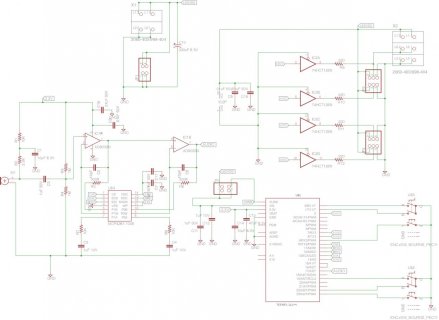
I've been working on a second revision of my board and I've attached the schematic here. I've added bypass capacitors, and will be trying to further isolate things when I lay out the board.

Here's my updated schematic:
lush.jpg
 
@Docedison,
I was thinking the grounding issue with my cable was that one side was acting like an antenna. Your point is good though. I will have to check to see if both grounds on my audio cable are indeed connected at the connector. Considering it was salvaged from headphones that is a possibility.

Yeah, on a bread board and all the added capacitance and antennas that adds it certianly can happen easily! ;)
 
@farman,
This is probably not related, but Vdd must be 4.5VDC for HCT chips. HC chips can be as low as 2VDC for Vdd. This is from the NXP docs BTW.
http://www.nxp.com/documents/data_sheet/74HC_HCT125.pdf

Like you observed it really should not be affecting noise because you see no different between Lipo and USB power at this time. If you start seeing weirdness at 3.7VDC on the HCT that may be why. Only inputs on CMOS chips need to be tied to something. Outputs can float.
 
Is there a low value (good high frequency performance) ceramic capacitor soldered close to the 74HCT125 power and ground pins?

Edit: Big high-value aluminum electroytics don't count. They have high ESR & ESL, so they have terrible high frequency response. You only get high frequency current from ceramic or poly film capacitors, with short leads connected close to the chip.
 
Last edited:
One stray thought.. is it possible to use an analog ground plane and a Pi section filter in the AVcc source. The analog ground plane must be grounded only at the same place as the digital ground and only there. This point must also be the power ground or return. in this manner the analog ground current returns at the same place as does the potentially noisy digital one, thus separating the noise from the audio stuff.
I'd also keep the mic wiring as short as possible and preferably shield it. Fast rise time pulses contain a lot of power.. and should be at all costs avoided by low level audio stuff. Small value (10 - 47 ohms) are also useful in series with high speed data lines and should ideally be as close to the data driving source as possible, combined with the inevitable stray capacitance they serve to slow the rise time of the signal and must be as small as is effective for noise reduction but not so big as to compromise speed.. this is also a place to try ferrite beads if the digital data is going off board.
This was an issue I dealt with many years back in designing a control head for a 450 MHz mobile phone.. It was the control lines for the synthesizer data lines that were carrying noise from the 150 Mhz synthesizer that fed the multiplier and power amp chain.. Even the display wiring was radiating some noise..

Doc
 
I'll make sure to use a 74HC125 instead of a 74HCT125 next time around. I didn't realize the difference.

I've currently got a .1uF ceramic cap across each of the discrete ICs on my board and I am going to have spots for a pair of 0805 capacitors on the new board for each of the three ICs. I am currently thinking of doing a pair of .01uF for each, but wasn't totally sure what values.

I believe the WS2811 protocol is running at 800kHz so it doesn't seem like it's that fast. Would 10 ohm resistors affect the signal enough to cause problems triggering the LEDs which I thought were already temperamental?

Also, unrelated, anyone know why I stopped getting responses emailed? I'm still subscribed but didn't get a response since August 25th.

Thanks
Dave
 
Yes, although 800 KHz isn't particularly fast it's rise time generates both multiples and fractional products of the data or clock noise.
small resistances (10 - 50 ohms) work with the stray circuit capacitive loading to slightly slow the rise time of the data/clock data thus reducing direct 'harmonics' of the frequency used for the clock/data bus transfer speed.
A part of the Bypass method is to render the PCB layout less resonant.
Each capacitor used as a bypass has different ESR/ESL characteristics. Different values help to cover the gray issues between the available parts and the best methods of applying those methods to your persistent noise issues. Making stable RF amplifiers, especially low level high power gain circuits are a most parallel comparison.. Many times Power traces and bypasses can form resonant circuits that are really difficult difficult to diagnose
A pulse in a time to frequency or Fourier transform will show the relative energy of both multiples and sub multiples.
However your issues appear to be more wiring, R + XL/Xc or grounding/bypass vs trace length/width issues or poor layout that brings the high gain audio stuff too close to the digital stuff. Separate power supplies and/or more modularization of your design might point you in the correct area..
The question is in three area's Sw design. PCB layout and power supply issues. I'm trying to address it as if I were training a new techie in trouble shooting methodology. Take Nothing for granted... Code is as complicated as circuit design and one will frequently mask each another. I call it "Tuning the Breadboard"
Knowing the parasitic parameters is a big plus in finding noise issues. most of mine were in ground loops, thus my emphasizing layout and shielding and bypassing.
Although it is a brute force approach it can be of help in understanding where and why mixed signal stuff is sometimes problematical.

Doc
 
Last edited:
With my current board I have a single decoupling cap solder across each IC, and tried using a capacitor probe and did find it reduced noise on the 3.3V line when I attached it to each of the supply pins so it feels like there's still some room there.

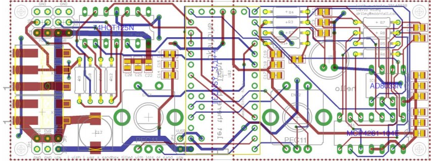
I've sent off my new board, and left spots for three capacitors for each of the 74HC125, AD8032 and the MCP4261 right next to the supply pins of each. I'm not quite sure what values I should set each to? I was thinking .1uF, .1uF, .01uF. I also separated the analog section from the digital section with a separate AGND/GND plane for each half.

Hopefully that sorts out my issues.

lush-brd.jpg
 
YES, You are on the right path and "Probing for Hot Spots" is the most effective tool to find the lack of proper decoupling (Bypassing).. a BIG plus is separating (Star topology) all supply points and ground returns to originate from one common point and MOST important the ground paths' as any ground noise is common to all that use the same common ground.
Good work and a great lesson...
High current loads and fast IC's require a minimum of a 100nF capacitor and a 10 nF capacitor with a 10 to 47 uF cap every three or so Ic's coupled to either a separate digital ground or better a substantial digital ground plane.
Analog Low noise circuitry requires a separate ground plane that returns to the main board ground only at the board current return.

Doc
 
Last edited:
AS a side note about bypassing.. The cost of pads or holes for bypass capacitors cost nothing to add except the room to place them, however it is very difficult to add them in a design that requires them but has no provisions for them.
The actual parts are Very cheap considering the time involved to "Cure" the issues caused by their absence.. adding "Hanging parts" is frequently more expensive from a manufacturing standpoint.
The last point is just because some designs don't seem to require them, although they are simply good electronics design practice to include them. It's called due diligence and is little different from developing stable code.
Further the lack of them Can and Will be a variable in final design stability.. ie one or two boards may not require them and some will require them.
This is a most variable condition and it depends on the layout and the individual part itself...
Not All of any IC families are necessarily totally equal.. Especially from different manufacturers selling the same parts.
Batch to batch variations are common... Too
Sometimes because of power supply and loading conditions (perhaps a different clock speed.. Loading or use) the capacitors are required/not required due to operating conditions or power supply capability or just parts from different manufacturer's
Code and Good Engineering practices. are very similar, Different disciplines, to be sure...
However poor code design and poor design practices are little different and sometimes hard to debug.
It is my practice to breadboard every piece of the "modules" and test them both electronically and performance..
Then I will order a "First Article" PCB.. test it to it's limits and then some.. before I either revise my PCB and or my code in order to make a preliminary design for field testing..
When the combination passes field testing is the time I will "Sign Off" on the design and them I still consider the design a "Prototype".... When 50 to 100 pass all field testing possible then I will release the design for production.. When I worked for a living this was my plan for success.
It is much easier to fix/modify 50 or 100 boards and correct the "gotcha's than it is to rework several hundred or thousand boards.
The Devil is Always in the details...
<End of Rant>

Doc

Doc
 
Last edited:
Status
Not open for further replies.
Back
Top