ILI9163C 128x128 TFT driver

Status
Not open for further replies.

sumotoy

Well-known member
ILI9163C 128x128 & ILI9340 240x320TFT driver
CIMG6810.jpg

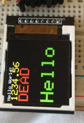
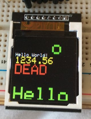
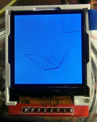
Here's a working driver for ILI9163C 1.44" 128x128 (but can works with other resolution's TFT) SPI TFT, prolly the most cheap display available. I got several on ebay for about less than 4 Euro (free expedition) but I've seen even cheaper.
Just search in ebay for "1.44" Red Serial 128X128 SPI Color TFT". This display use the ILI9163C chip that has no know library for Arduino and Teensy and this probably the reason why it's so cheap. Thanks to Paul's fast SPI routines I build up this library that drive really fast this display and it's fully compatible with Adafruit ones (I'm using Adafruit_GFX) so it can be easily used in different projects without learn from scratch commands.
The maker of those display's (a chinese for sure) forgot to set the hardware addressing for fix the memory map to a certain resolution (in this case 128 x 128) and leaved at 128 * 160 so this display showed big pixel addressing problems that fortunatly I fixed after a couple of days over the damn clumsy datasheet.
Here's a video that shows it with a Teensy3.1 at 24Mhz/SPI

Can be really good for experimenting without spend a lot of money for prototypes, also I like the square resolution, useful for gauges. Remember that it's extremely cheap display!
Hope it's useful.

Edit 1/6/2014:
Added ILI9340 and ILI9340C library that uses Paul's Native SPI (tipically 2.2" 240*320 display's from Adafruit and on Ebay, RED pcb ones).
On GitHub:
https://github.com/sumotoy/TFT_ILI9340/

On Github:
https://github.com/sumotoy/TFT_ILI9163C

 
Last edited:
Thank you sumotoy for all of your hard work. I have a couple displays on order
.......anxious to try out your lib.
 
Hi again sumotoy, received my displays today but I have not had any luck getting one to work Using a Teensy 3.1 with
teensyduino 1.19 rc2. The pinout on the display is: LED, SCK, SDA, A0, RESET, CS, GND, and VCC. I am powering it with
3.3 vdc and using pwm for the LED backlight. Can you suggest a hook up for the Teensy 3.1 using your libs ?? The text
on the back of the pcb is: 1.44' SPI 128*128 V1.1.

EDIT: Never mind sumotoy, I figured it out. I think you were probably assuming that no 'SPI idiots' like me would
be trying to use your libs. It's working fine now. Teensy 3.1 pins to LCD: using the t3.1's 3.3 vdc out to power
the display, analogWrite(3,150) to LED, pin 13 to SCK, pin 11 to SDA, pin 9 to A0, pin 15 to RESET, pin 10 to
CS. It sure is a nice display for the price. Thanks again for the libs.
 
Last edited:
Cool!
There's also the library for ILI9340C (link on top), this time 240x320, around 6 buks on Ebay.
 
Your lib seems to work pretty well, but with my setup (described above), display.clearScreen() causes a bit of flicker.
Is there any way to stop the flicker ??
 
This can be because the data is sent so fast that display react it's slower than data processed by controller. I got the same problem with the 3d cube example that require a complete screen refresh every frame, it flickers at the bottom.
Sending data much slow will give better results but certenly it's not acceptable solution.
I found that tuning some of the initialization values give better (or worst) results so I will investigate this weekend.
 
Hello,
I have also bought one of these screens but am having difficulty getting it to work.
I'll try to be as clear as I can. It's the same screen, on the back is printed "1.44' SPI 128*128 V1.1", the board itself is black.

sumotoy you mentioned on your github that one of your friends also had the black version but needed to change something,
what did they do to get it working?

As it sits right now, I've got the ILI9163C and Adafruit_GFX libraries and have the screen connected to an arduino uno through a level converter as follows
Code:
Printed		What I		Arduino
Name		Think it is	Connection

LED		(BACKLIGHT)	3.3v
SCK		(SCLK)		pin 13
SDA		(MOSI)		pin 11
A0		(DC)		pin 9
RESET		(RESET)		pin 8
CS		(CS)		3.3v
GND		(GND)		GND
VCC		(VCC)		3.3v

When I load the test program it doesn't appear to do anything, the screen is white but just looks the same as when the backlight is on.

I'm really stuck at this point and would really appreciate any help anyone can give.

Thanks in advance
 
can you give me the link where you buy it? Have to check if I can find any info about it, maybe different chipset?

Edit:
You have connected CS to 3V3? It will never work like that!
CS it's a part of the SPI, tied to + will block any SPI communication with the display

You should connect:

SCK -> 13 (cannot change this)
SDA -> 11 (cannot change this)
A0(DC) -> 9 (you can change but not all pins are usable, see library)
CS -> 10 (you can change but not all pins are usable, see library)
RESET -> 8 (any pin, you can also avoid, check library .h)


TFT_ILI9163C(uint8_t cspin,uint8_t dcpin,uint8_t rstpin);

will be:

TFT_ILI9163C tft = TFT_ILI9163C(10, 9, 8);

Try like this!

Sorry for delay, I'm in vacation in an island in Greece and internet not always available, also a lot of power loss, last day 12 hour of blackout.
 
Last edited:
Hi sumotoy,

Thanks for your reply.
Yes bit of a dumb moment on my part, it's been a while since I did anything with spi and I forgot that CS is active low, d'oh!

Anyway unfortunately that didn't solve my issue, however I found that if I run the logic at 5v the display works, but im a little hesitant to run it like this,
can you confirm if this is ok for this chip? I looked through the data sheet and I couldn't find any part that said the chip was 5v tolerant.

Here is the link to the screen, I believe that is is the same as the one you mentioned your friend having because this also has slightly different memory addressing.
http://www.ebay.co.uk/itm/New-1-44-Serial...

Thanks and enjoy your holiday!
 
Tft 128 x 128

Hi,

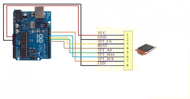
I tried the driver above and the examples and can't for the life of me get it to work ! I think I'm having a similar problem that Hallam had. I had tried attaching an image of the setup:
TFT ARDUINO.jpg

Basically it is:
VCC = 3.3V
GND = 0V
LED = 3.3V
RESET = Arduino Pin 8
CS = Arduino Pin 10
A0 = Arduino Pin 9
SDA = Arduino Pin 11
SCK = Arduino Pin 13

Any help would be appreciated as all I seem to get is the Back light :(
 
SumoToy sounds like a really cool display.

Were you able to write any bitmaps to it? I would be cool to learn how fast that chip can write a bitmap.

Also if you want to run your Teensy at 96mhz just add a delay to the Shiftout function. Here is my example for a Digole display.
//Rewrite the Shiftout function for the Teensy 3.1 clock speed
//Teensy MHz || delayMicroseconds
// 24 || 5
// 48 || 10
// 72 || 20
// 96 || 25
void shiftOut2(uint8_t dataPin, uint8_t clockPin, uint8_t bitOrder, uint8_t val){
uint8_t i;

for (i = 0; i < 8; i++) {
if (bitOrder == LSBFIRST)
digitalWrite(dataPin, !!(val & (1 << i)));
else
digitalWrite(dataPin, !!(val & (1 << (7 - i))));

digitalWrite(clockPin, HIGH);
digitalWrite(clockPin, LOW);
delayMicroseconds(25);//delay goes here
}
 
Linkpad,

In your schematic you've got your backlight linked to ground.
But if you've wired it up as you have written it, then that is the same as the way I did it.
Have you changed the pins in the example code? As I remember it the reset pin is set as 14 in the code, so you must change it to 8.

If you post your code i'll have a look.

Thanks Hallam I did notice that too in the code I will try changing it, as there is no pin 14 on a Uno.
 
On the Uno, pin14 is A0, just like it is on the Teensy 3.1.

On other chips (Leonardo, Mega, etc.), pin14 may not map into A0
 
Now i'm confused, i'm struggling to understand how pin A0 = 14 on the arduino ? Now my arduino software won't load anymore and crashes.
 
View attachment 2043

Here's a working driver for ILI9163C 1.44" 128x128 (but can works with other resolution's TFT) SPI TFT, prolly the most cheap display available. I got several on ebay for about less than 4 Euro (free expedition) but I've seen even cheaper.
Just search in ebay for "1.44" Red Serial 128X128 SPI Color TFT". This display use the ILI9163C chip that has no know library for Arduino and Teensy and this probably the reason why it's so cheap. Thanks to Paul's fast SPI routines I build up this library that drive really fast this display and it's fully compatible with Adafruit ones (I'm using Adafruit_GFX) so it can be easily used in different projects without learn from scratch commands.
The maker of those display's (a chinese for sure) forgot to set the hardware addressing for fix the memory map to a certain resolution (in this case 128 x 128) and leaved at 128 * 160 so this display showed big pixel addressing problems that fortunatly I fixed after a couple of days over the damn clumsy datasheet.
Here's a video that shows it with a Teensy3.1 at 24Mhz/SPI

Can be really good for experimenting without spend a lot of money for prototypes, also I like the square resolution, useful for gauges. Remember that it's extremely cheap display!
Hope it's useful.

Edit 1/6/2014:
Added ILI9340 and ILI9340C library that uses Paul's Native SPI (tipically 2.2" 240*320 display's from Adafruit and on Ebay, RED pcb ones).
On GitHub:
https://github.com/sumotoy/TFT_ILI9340/

On Github:
https://github.com/sumotoy/TFT_ILI9163C


Hi there , thank you for providing this amazing library , is there anyway to convert it for use on stm33f4 or any other arm cortex-m3/m4 MCU ??
 
I'm using this library to display images from an SPI flash chip and it is working well with an Arduino Mini. Now I want to move to a Teensy 3.1, but the Teensy SPI code is quite different and I can't seem to figure out how to use an additional SPI device. The display works on the Teensy, and with a separate upload I can read from the flash chip, but I don't know how to put them together. Can anyone give me any hints?
 
Good question, even the tons of libraries for Flash chips for Arduino are not reliable at all, for example, I have several 512/1024 chip from Microchip and still now I cannot get working on my UNO. Some chip uses paged memory handle, some use direct addressing, so basically every chip needs it's own library. Are you using this library with Arduino Mini and witch SPI flash chip?
 
I'm using this library to display images from an SPI flash chip and it is working well with an Arduino Mini. Now I want to move to a Teensy 3.1, but the Teensy SPI code is quite different and I can't seem to figure out how to use an additional SPI device.

If you post the actual (complete) code, I'll take a look....

I really can't offer any useful advise based only on this question, without the code or even the chip's part number.
 
Good question, even the tons of libraries for Flash chips for Arduino are not reliable at all, for example, I have several 512/1024 chip from Microchip and still now I cannot get working on my UNO. Some chip uses paged memory handle, some use direct addressing, so basically every chip needs it's own library. Are you using this library with Arduino Mini and witch SPI flash chip?

I am using this TFT library with the Mini and the flash chip is a WinBond W25Q80BV 1MB flash. I got the code for accessing the flash chip from this article http://www.instructables.com/id/How-to-Design-with-Discrete-SPI-Flash-Memory/. Here's the code that works on the Mini:

Code:
#include <SPI.h>
#include <Adafruit_GFX.h>
#include <TFT_ILI9163C.h>
#include <Serial.h>

// WinBond flash commands
#define WB_READ_STATUS_REG_1  0x05
#define WB_READ_DATA          0x03

#define __CS 7
#define __DC 9
#define __RST 8

TFT_ILI9163C display = TFT_ILI9163C(__CS, __DC, __RST);

uint16_t displayRows = 128;
uint16_t numImages = 3;
byte pageBuf[256];

void setup() {
  display.begin();
  display.setBitrate(24000000);
  display.clearScreen();
  pinMode(3, OUTPUT);  // backlight control
  analogWrite(3, 255);
}

void loop() {
  for (int i = 0; i < numImages; i++) {
    for (int p = 0; p < displayRows; p++) {
      read_page(p + (i * displayRows), pageBuf);
      display.writedatabuffer(p, pageBuf);
    }
    delay(5000);
  }
}

/* Read the WinBond W25Q80BV 1MB SPI flash.
   Code adapted from Instructables article 
    http://www.instructables.com/id/How-to-Design-with-Discrete-SPI-Flash-Memory/
*/

void read_page(word page_number, byte *page_buffer) {
  digitalWrite(SS, HIGH);
  digitalWrite(SS, LOW);
  SPI.transfer(WB_READ_DATA);
  // Construct the 24-bit address from the 16-bit page
  // number and 0x00, since we will read 256 bytes (one
  // page).
  SPI.transfer((page_number >> 8) & 0xFF);
  SPI.transfer((page_number >> 0) & 0xFF);
  SPI.transfer(0);
  for (int i = 0; i < 256; ++i) {
    page_buffer[i] = SPI.transfer(0);
  }
  digitalWrite(SS, HIGH);
  not_busy();
}

void not_busy(void) {
  digitalWrite(SS, HIGH);  
  digitalWrite(SS, LOW);
  SPI.transfer(WB_READ_STATUS_REG_1);       
  while (SPI.transfer(0) & 1) {}; 
  digitalWrite(SS, HIGH);  
}

display.writedatabuffer() is just a function I added the TFT library to speed up writing each row:
Code:
void TFT_ILI9163C::writedatabuffer(uint16_t y, uint8_t *buf){ 
    setAddrWindow(0,y,_width-1,y);
	*rsport |=  rspinmask;
	*csport &= ~cspinmask;
    // assume 256 byte buffer
    for (int b = 0; b < 256; b++) {
        spiwrite(buf[b]);
    }
	*csport |= cspinmask;
}

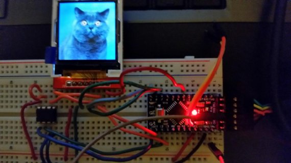
This is working well on the Mini as the attached image shows.

ILI9163C_W25Q80BV_Mini.jpg

But I can't use the same code to access the flash chip when using the Teensy 3.1 - it looks like this TFT library uses advanced SPI features and the code is very different. What I want to know is how to write the equivalent code for the flash chip on the Teensy.

Hope this is clear enough.
 
I have posted ths on the Aurdrino forum but it may well be better suited to here as it is really a question about the sumotoy code. If your unhappy please just remove it. Thanks, Paul


Hi all.

I have been playing with a 1.44" 128x128 TFT ILI9163 (Black PCB) display for a week. I have it working under a couple of different graphics libraries and drivers but I have a strange issue with one of them.

Hardware: 1.44 128x128 TFT ILI9163 display screen *ebay link
Board: Arduino UNO

Wiring

sck - pin 13
reset - pin 9
sda - pin 11
cs - pin 8
A0 (DC) - pin 10
GND - GND
VCC - VCC
LED - 3.3v


Code setup

#define __CS 8
#define __DC 10
#define __RST 9


Setup 1

Driver & Graphics Library: Libraries, Driver & Scratch

This is built on work done by Paul Kourany and his Multi Font GFX Library (mfGFX Library) on github Here *which in turn is a fork of the Adafruit GFX library.


The result . . .

Result_1.jpg


All good!


Setup 2


Driver: TFT_ILI9163C Driver Library by Sumotoy
Graphics Library: Adafruit-GFX-Library

This is the thread by Sumotoy that explains it all Sumotoy ILI9163C driver

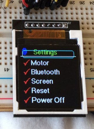
The result . . . . .

Result2_1.jpg
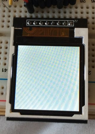
Reset


Result2_2.jpg
errrr sort of reset


Result2_3.jpg
the top part of the screen has not been cleared from the previous project code


Result2_4.jpg
still the same

Result2_5.jpg
now its clear. As this write to the screen starts from the bottom, it looks like the top got erased for that reason.


Result2_6.jpg
this time the top area is written to with new display data. Again the write to the screen starts from the bottom.


Result2_7.jpg
the top area of the screen is still showing the previous write. This time the write is from the top of the screen.


So it looks like my 'Setup 2' is not referencing the top screen co-ordinates correctly.

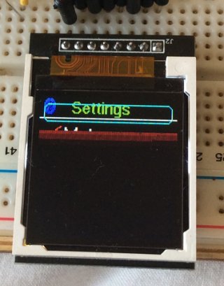
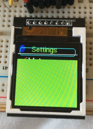
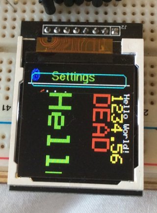
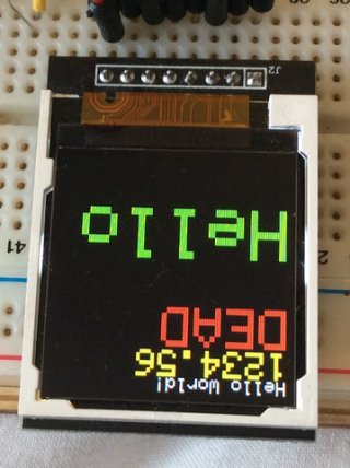
In Sumotoys first comment about this display he says . . 'The maker of those display's (a chinese for sure) forgot to set the hardware addressing for fix the memory map to a certain resolution (in this case 128 x 128) and leaved at 128 * 160 so this display showed big pixel addressing problems that fortunatly I fixed after a couple of days over the damn clumsy datasheet'

If this is relevent or not I do not know as he says he has sorted it. I have also checked that the library is setup for the black display and not the red one.


I have only been playing with Audrino for a couple of weeks so it may be that I have just missunderstood something but all and any help with this problem would be very much appreciated.

Regards, Paul
 
Last edited:
Status
Not open for further replies.
Back
Top