You are using an out of date browser. It may not display this or other websites correctly.
You should upgrade or use an alternative browser.
You should upgrade or use an alternative browser.
AGND or GND
- Thread starter gripner
- Start date
- Status
- Not open for further replies.
PaulStoffregen
Well-known member
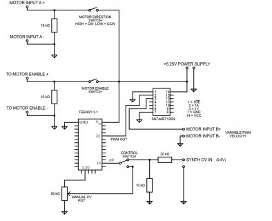
Do I have my grounds right in this circuit?
That's a good question. All your ground symbols look identical, so how can anyone know which you're connecting to GND and which you're connecting to AGND?
donkeyahoy
Well-known member
I have all them going to the same GND, the upper left on the Teensy.
No good?
No good?
donkeyahoy
Well-known member
Jp3141
Well-known member
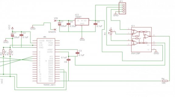
You are correct -- REF 'offset's the output. Its need depends on the polarity of the signal from your load cell. If it changes polarity, then with REF at AGND, the ADC can't convert the negative voltage. Biasing REF higher allows you to work with both polarities (including no-load offset of the load cell). Of course, your ADC result then needs the REF value subtracted (use another ADC channel to convert this).
Jp3141
Well-known member
It looks correct; REF at AGND or VREF depends on your needs.
It isn't critical in this circuit to connect the INA's GND to AGND. In general there's a tradeoff -- connecting to GND makes the output slightly dependent (depends on the INA's power supply rejection ratio) on noise there; connecting to AGND means that the INA's DC current consumption flows through that connection, and unless you are careful could add a DC (temperature dependent) offset to the system. In your case, this is probably not likely to be an issue, so AGND might be theoretically more preferable, but likely not detectable.
It isn't critical in this circuit to connect the INA's GND to AGND. In general there's a tradeoff -- connecting to GND makes the output slightly dependent (depends on the INA's power supply rejection ratio) on noise there; connecting to AGND means that the INA's DC current consumption flows through that connection, and unless you are careful could add a DC (temperature dependent) offset to the system. In your case, this is probably not likely to be an issue, so AGND might be theoretically more preferable, but likely not detectable.
Jp3141
Well-known member
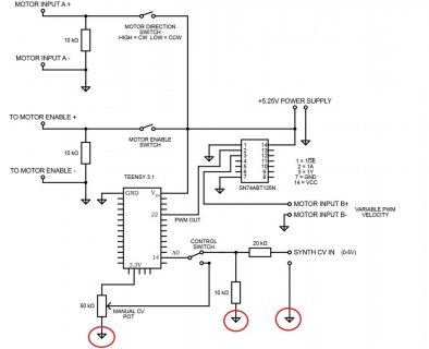
Looks correct with the circled going to AGND on the Teensy. Add a capacitor (0.1 uF ceramic) from the ADC input (A0 ?) to AGND to filter RF and interference.
You have sufficient ADC channels to connect the pot and other input to dedicated inputs (each with a 0.1 uF) -- do you need the switch ? (or is it used to set which mode the system is in ?).
Keep the motor and power supply wiring separate from Teensy until you join all those wires at a single point, and connect that point to the Teensy's GND (This is called a 'star' connection).
Short circuits and errors happen -- if your wires are long, and the motor runs from over 5 V, consider adding a R (1 k ?) in series with the motor enable switch -- that way if the pin gets shorted to a higher voltage it won't immediately fry your components.
What voltage is at motor input A ? The Teensy can't take more than about 5.5 V. If the voltage is higher, then insert a regulator (e.g. LM7805) in there.
PaulStoffregen
Well-known member
If you're looking for a low noise reading on the pot, you'll probably want to use a lower value, like 5K or even 1K. Lower source impedance really helps.
Of course, connect the pot to AGND.
But really, most humans can't mechanically manipulate a single turn pot to highly precise positioning. In other words, without looking at the numbers, try turning the pot to a particular angle 5 times, and then look at the readings. You'll quickly discover human dexterity is the real resolution limit in using a pot for any sort of user input. Even 8 bits is probably more resolution than needed.
But if you really want maximum electrical performance, use a lower impedance pot and connect it to AGND.
donkeyahoy
Well-known member
Looks correct with the circled going to AGND on the Teensy. Add a capacitor (0.1 uF ceramic) from the ADC input (A0 ?) to AGND to filter RF and interference.
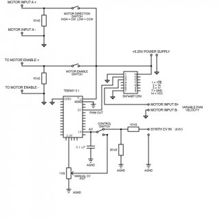
Ok added it to the circuit diagram. Did I wire it right? See pic.
You have sufficient ADC channels to connect the pot and other input to dedicated inputs (each with a 0.1 uF) -- do you need the switch ? (or is it used to set which mode the system is in ?).
Yes, I would like to keep the switch. It lets me choose the mode. Correcto!
Keep the motor and power supply wiring separate from Teensy until you join all those wires at a single point, and connect that point to the Teensy's GND (This is called a 'star' connection).
This motor has a separate, dedicated large power supply that is not shown in this circuit. Not sure if it ever will join with this Teensy circuit. I'll check the manual. Thank you for this 'star' technique. I will keep it in mind for the future.
Short circuits and errors happen -- if your wires are long, and the motor runs from over 5 V, consider adding a R (1 k ?) in series with the motor enable switch -- that way if the pin gets shorted to a higher voltage it won't immediately fry your components.
All short wires.
What voltage is at motor input A ? The Teensy can't take more than about 5.5 V. If the voltage is higher, then insert a regulator (e.g. LM7805) in there.
Only 5.25V. This enable input A only needs to be a digital high over 5V to let the motor know to activate. It is not power.
Thank you so much for the help!! I really appreciate it. It would take me days to research and find this info. It saves so much time asking the experts!
donkeyahoy
Well-known member
If you're looking for a low noise reading on the pot, you'll probably want to use a lower value, like 5K or even 1K. Lower source impedance really helps.
Ok. Changed it to 1K. Would this same theory apply to my voltage divider area? This is where the analog control voltage from the synthesizer is being reduced from the 0-5V to the 0-3.3V needed. If so what values would you recommend?
Of course, connect the pot to AGND.
Ha! I guess that's why they call it analog ground. Sorry, didn't hear of it until now.
But really, most humans can't mechanically manipulate a single turn pot to highly precise positioning. In other words, without looking at the numbers, try turning the pot to a particular angle 5 times, and then look at the readings. You'll quickly discover human dexterity is the real resolution limit in using a pot for any sort of user input. Even 8 bits is probably more resolution than needed.
You are absolutely correct here. I was thinking of this issue earlier. It is especially important to match the speed when I record on the tape and later try to play it back at the same speed. After I figure out all the basics, the plan is to hook up one of those graphic displays to show the current setting.
But if you really want maximum electrical performance, use a lower impedance pot and connect it to AGND.
Thanks Paul!! Awesome product and excellent support! Thanks for putting up with my noobness.
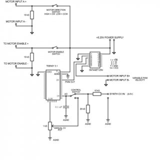
donkeyahoy
Well-known member
So instead of using a pot to set the speed, have a small display and two buttons - 'faster' and 'slower'. That way you can get to precisely the same speed.
Fantastic idea! I would love that button setup. Still would like to keep the pot as an option at the same time. It is good for doing rapid hand sweeps during some applications. The buttons would be a grande bonus that is very exciting. You could also have a dial that would set the increment amount of the buttons? I'm definitely going to need all this!
Man I have some work to do. Thank you for that idea. Buttons with the digital read out is going to be real sweet.
These three circled in red should go to AGND?
Yes.
Probably a good idea to add a couple of schottky diodes on the input to protect against CV outside the range 0..5V (could be ±12V or ±15V depending on what synth format you are using). Also, unless your synth uses banana sockets, a switched jack could be used instead of the manual switch. So you get the CV from the pot if nothing is patched, and the patched CV if it is.
donkeyahoy
Well-known member
Yes.
Probably a good idea to add a couple of schottky diodes on the input to protect against CV outside the range 0..5V (could be ±12V or ±15V depending on what synth format you are using). Also, unless your synth uses banana sockets, a switched jack could be used instead of the manual switch. So you get the CV from the pot if nothing is patched, and the patched CV if it is.
Thanks Nantonos!! Glad to see another familiar with analog synths! Since you are experienced with synth control voltage could you answer a few more questions about this area, please?
DIODES
1. What size diodes would you recommend? Do you have a part #? So just place 2 diodes in series before the Teensy A0 pin? This won't degrade my signal at all?
Yes my synth cv possibilities are around ±10V. I was mainly going to be careful and use only the +0 to 5V outputs, but if it wouldn't hurt to have the diodes, I will use them. Nice to have a safety feature.
VOLTAGE DIVIDER AREA
2. Should I use lower resistors when dividing my analog cv from the synth? Paul said the manual pot option should be 1K for less noise. Right now the other control option (synth cv) uses 10k and 20k resistors in this divider area.
OTHER
3. Does that synth cv out circuit area look okay. I am unfamiliar with the actual circuits needed for taking the cv from a synth.
* Great idea about the switched jack! Will do. Streamlines the design! Very nice.
Thanks again. Happy patching!
'Being careful' in the context of a modular synth means you are one "oops, wrong patchcord" from a fried Teensy.
Not in series (that would affect the signal due to the voltage drop across the diodes). Instead, one diode from the ADC input to the positive rail, and one from the ADC input to the negative rail (ground, in this case); oriented so that they do not normally conduct. If the input voltage goes more than one diode drop below ground, or more than one diode drop above the positive rail, the diode conducts and shunts the voltage away from the ADC input. Schottky diodes are used because of their low voltage drop. 1N5817 (available from various manufacturers) is commonly used. The forward voltage depends on current and temperature but is in the range 0.1 to 0.3V (instead of 0.6V for a normal silicon diode).
To limit the current if the diodes conduct, a resistor should be used before the diodes. Don't make this too high or the ADC function will be affected; 1k is a good value.
Here is an example circuit using this configuration (that is not my circuit, but it uses this principle).
Yes, you should either use lower value resistors or follow it with a rail to rail op-amp. Either way, the ADC needs to be driven from a moderately low impedance.
The other nice thng about sending the pot wiper value to the jack switch input is that it avoids the condition where there is no cable connected, the switch is in the 'jack' position and so the input is floating at an undetermined voltage. This way, there is always a defined value. Note that the wiper voltage now goes through your voltage divider, so the top of the pot should go to +5V or so.
I can't speak to the rest of your circuit that drives motors. But I am curious as to what this circuit is for. CV controlled Leslie speaker? Animatronic lighting?
Last edited:
donkeyahoy
Well-known member
'Being careful' in the context of a modular synth means you are one "oops, wrong patchcord" from a fried Teensy.
Not in series (that would affect the signal due to the voltage drop across the diodes). Instead, one diode from the ADC input to the positive rail, and one from the ADC input to the negative rail (ground, in this case); oriented so that they do not normally conduct. If the input voltage goes more than one diode drop below ground, or more than one diode drop above the positive rail, the diode conducts and shunts the voltage away from the ADC input. Schottky diodes are used because of their low voltage drop. 1N5817 (available from various manufacturers) is commonly used. The forward voltage depends on current and temperature but is in the range 0.1 to 0.3V (instead of 0.6V for a normal silicon diode).
To limit the current if the diodes conduct, a resistor should be used before the diodes. Don't make this too high or the ADC function will be affected; 1k is a good value.
Here is an example circuit using this configuration (that is not my circuit, but it uses this principle).
Yes, you should either use lower value resistors or follow it with a rail to rail op-amp. Either way, the ADC needs to be driven from a moderately low impedance.
The other nice thng about sending the pot wiper value to the jack switch input is that it avoids the condition where there is no cable connected, the switch is in the 'jack' position and so the input is floating at an undetermined voltage. This way, there is always a defined value. Note that the wiper voltage now goes through your voltage divider, so the top of the pot should go to +5V or so.
I can't speak to the rest of your circuit that drives motors. But I am curious as to what this circuit is for. CV controlled Leslie speaker? Animatronic lighting?
Thank you so much! This is all very clear now and makes much sense. I will implement these circuit design techniques immediately. Thank you again for the invaluable information!!
My project is a voltage controlled tape loop motor that sits on top of a reel-to-reel. The tape is advanced by the new motor and capstan up top but continues to use the tape head below. The motor is a fancy servo type that can change speeds close to instantaneously from 0-4000 rpm in both directions. It is coming along nicely. Used for electronic music, experimental music, Musique concrète, or noise music. Good for tape loops (obviously), sound sample creation, and tape delay. Here are the pictures :
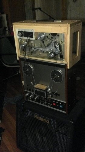
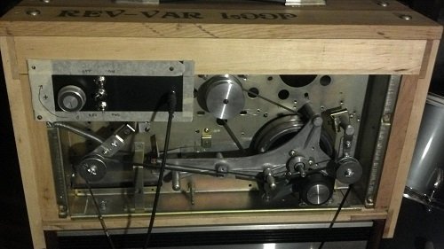
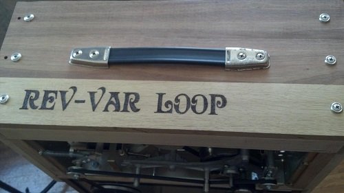
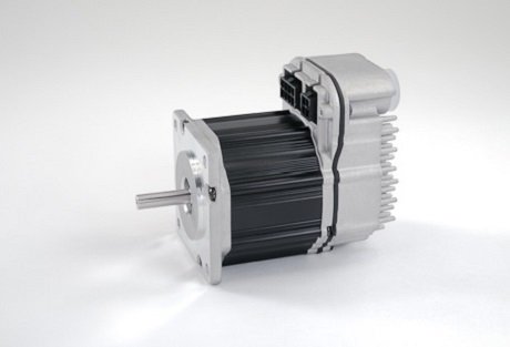
cheers!
donkeyahoy
Well-known member
Voltage controlled musique concrète, excellent. Thanks for the explanation and photos! Delia Derbyshire would be astonished.
Delia rules! That Dr. Who intro is awesome.
Nantonos, does this circuit for the cv area area look correct? I tried to implement all your suggestions. Could you double check it for me?
Thanks a million!
The first voltage divider area is to reduce the 5.25 V from the power supply to 5.0 V. Then the manual pot control should be disabled if the plug is inserted. Next is the second voltage divider area to take the 0-5.0 V (either from the external plug or pot) and reduce it to the 3.33V for Teensy. Diodes for protection and capacitor for cleaning. All using the AGND except at the power supply which goes to the Teensy GND.
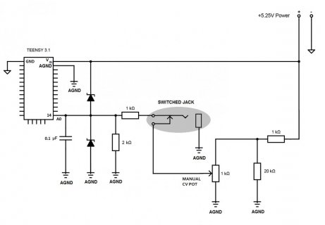
Jp3141
Well-known member
Your V divider for the pot won't work as you expect with a 1k pot.
1) is it really a 1k pot ? Usually 'random' pots are 5k or 10k.
2) whatever it is, to reduce the 5.25 V (don't assume it's precisely 5.25), you can just put a R in series (where your 1k is), but don't need the R in parallel (20k). To reduce the pot's max. output to (say) 5 V would need an R of 1/20 the pot's resistance (or more). Play it safe -- if you do have a 1k pot, use 100 Ω etc.
3) The 1k & 2k divider further interfere with the signal from the pot (think of the pot being only able to drive with 1k -- you have a 1k+2k load). Make this R divider ~ 10x the pot's resistance (e.g. 10k & 20k). The pot action will still be slightly non-linear (i.e. voltage won't precisely increase linearly with rotation), but the difference is small. If it was important, you could linearize it by calculating the exact transfer function of the circuit. As-is, the 1k&2k , 1k pot and 1k & 20k in the 5.25 V line mean that the maximum output you will get is not 3.3 V, but about 1.47 V.
3) Remember all your components have tolerances (pots could be +/- 20 %), the other resistors could be 5 %. Don't divide to get exactly 3.3, but leave some margin (10 %). Equally, you don't really have to have 5 V on the pot and then divider down again.
So -- if you have a 1k pot do this:
1k from the 5.25 -> 100 Ω
remove the 20k
the 1k & 2k divider should be 10x -- 10k & 20k, but add some margin, so use 12k and 20k. Or add more margin and use 15k & 20k, and remove the 100 Ω.
If the pot is another value, just scale all the above.
Last edited:
Nantonos, does this circuit for the cv area area look correct? I tried to implement all your suggestions. Could you double check it for me?
It isn't correct.
The first voltage divider area is to reduce the 5.25 V from the power supply to 5.0 V.
By itself, it would do that. But then the pot is in parallel with the second resistor so what you have is a resistive divider of 1k and (1k in parallel with 20k) 0.95k. That takes the 5.25 down to 2.69V!
Also, the current through that 1k pot is 2.6mA.
You would be better with say a 20k pot, keep the 1k, drop the 20k resistor. Now the wiper goes from 0V to 5V and the current is 250μA.
You have used the symbol for a Zener diode (ah, so did the circuit I linked to, didn't notice). These are not the same as Schottky diodes.Then the manual pot control should be disabled if the plug is inserted. Next is the second voltage divider area to take the 0-5.0 V (either from the external plug or pot) and reduce it to the 3.33V for Teensy. Diodes for protection and capacitor for cleaning. All using the AGND except at the power supply which goes to the Teensy GND.
As long as you use the correct type, the symbol on the schematic doesn't matter of course.Otherwise, that part looks good.

- Status
- Not open for further replies.


